EAGLE CONTROLLER – INSTALLATION & COMMISSIONING INSTRUCTIONS
7 EN1Z-0970GE51 R0918
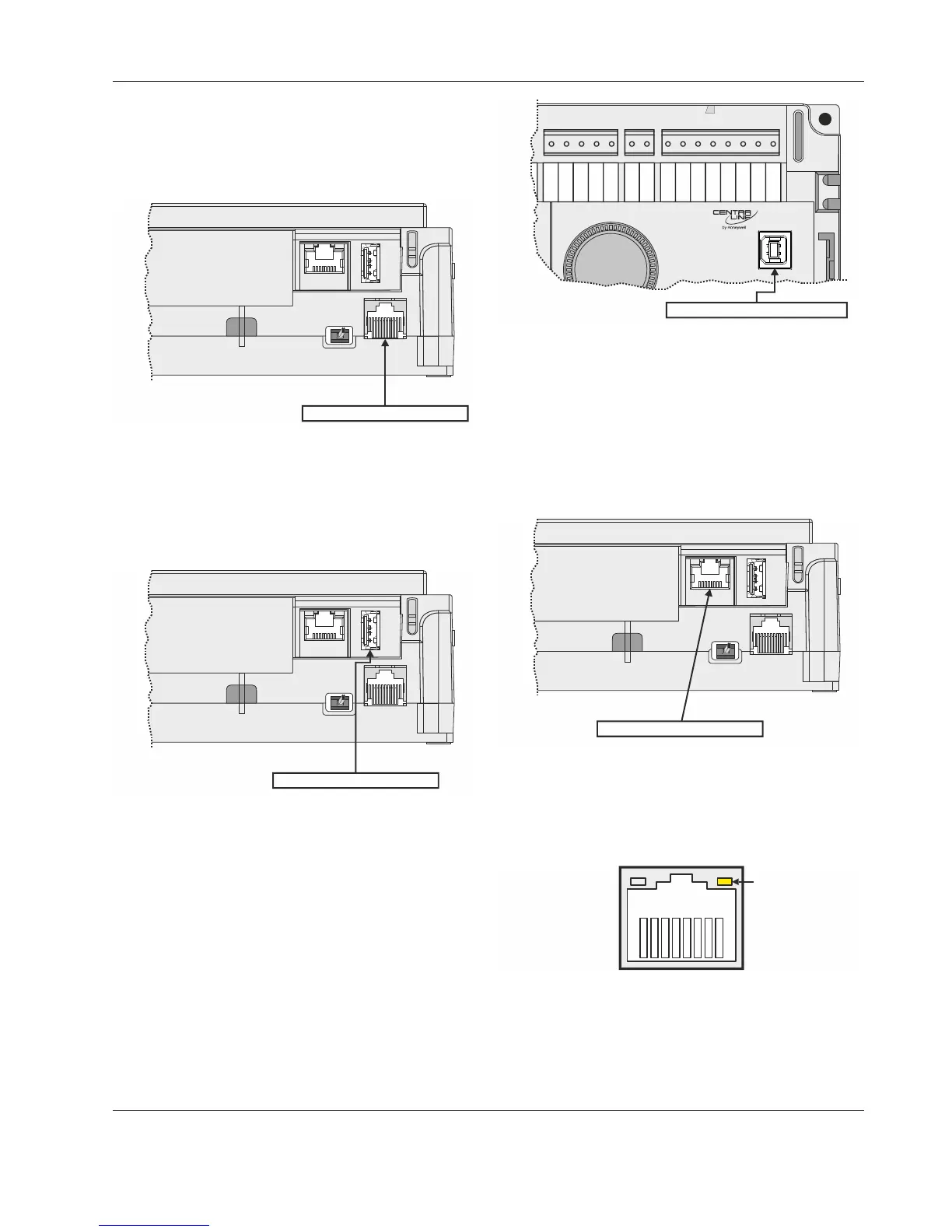
RS232 / RJ45 Socket
Via its RS232 / RJ45 socket, the EAGLE Controller can be
connected (using an XW586 cable) to a PW M-Bus Adapter
and thus to M-Bus networks. See also section "M-Bus
Connection" on pg. 33.
RS232-RJ45 SOCKET
J1 J8
Fig. 5. RS232 / RJ45 socket
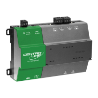
USB 2.0 Host Interface
Via its USB 2.0 Host interface, the EAGLE Controller can be
connected to, e.g., the IF-LON External Interface Adapter and
thus to L
ONWORKS networks. Max. 500 mA, high speed. See
also section "LonWorks Communications" on pg. 27.
USB 2.0 Host Interface
J1 J8
Fig. 6. USB 2.0 Host interface
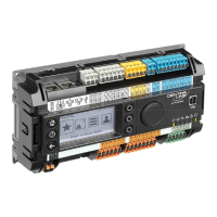
USB 2.0 Device Interface
All models of the EAGLE Controller are equipped with a USB
2.0 Device Interface at the front. This interface is for con-
nection to CARE / XW-Online and web browsers, CL-Touch,
or other 3
rd
-party touch panels.
BI1
BI2
BI3
BI4
GND
UI1
UI2
UI3
UI4
UI5
UI6
UI7
32 33 34 35 36 37 38 39 40
41 42
43
44
45 46
UI8
47
n.a.
UI9
UI10
USB 2.0 Device Interface
Fig. 7. USB 2.0 Device Interface
A standard USB type-B connector can be inserted into this
USB 2.0 Device Interface. This USB 2.0 Device Interface is
the recommended interface for connection to CARE.
Ethernet / RJ45 Socket
All models of the EAGLE Controller (except CLEA2014B21
and CLEA2014B31) are equipped with an Ethernet / RJ45
socket featuring one LED.
J1 J8
Ethernet / RJ45 socket
Fig. 8. Ethernet / RJ45 socket (CLEA2000Bxx,
CLEA2014Bx2, and CLEA2026Bxx, only)
This Ethernet / RJ45 socket is a 10/100-Mbaud Ethernet
interface permitting communication (as per IEEEC 802.3) on
BACnet IP networks.
LINK/ACT.
Fig. 9. Ethernet / RJ45 socket