EAGLE CONTROLLER – INSTALLATION & COMMISSIONING INSTRUCTIONS
EN1Z-0970GE51 R0918 8
NOTE: The Ethernet / RJ45 socket is usually earth-
grounded. For additional information on earth
grounding, see also "Appendix 1: Earth Grounding"
on pg. 36.
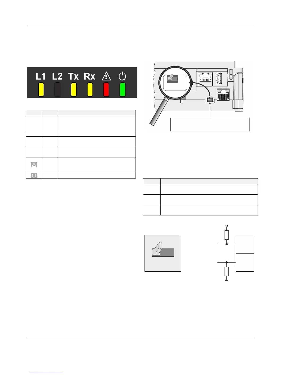
LEDs
The EAGLE Controller features the following LEDs:
Fig. 10. EAGLE Controller LEDs
Table 4. EAGLE Controller LEDs
symbol
color function, description
L1 yellow
application-specific LED indicating status
information ("Cooling Mode", "Heating
Mode" "Service Interval" etc.)
L2 -- Not used.
Tx yellow
RS485-1 status LED indicating trans-
mission of communication signals.
Rx yellow
RS485-1 status LED indicating reception
of communication signals.
!
red
status LED indicating hardware problems,
lack of application, sensor failure, or Panel
Bus failure
green power LED
See also section "EAGLE Controller Troubleshooting" on
page 35 for a detailed description of the behaviors of the Tx
and Rx LEDs, the status LED, and the power LED and their
meanings.
RS485 Interfaces
General
The EAGLE Controller features two RS485 interfaces:
RS485-1 (consisting of push-in terminals 24 [GND-1], 25,
and 26) is isolated and can be used for BACnet MS/TP
bus, Panel Bus, or Modbus RTU Master communication.
RS485-2 (consisting of push-in terminals 29, 30, and 31
[GND-2]) is non-isolated (i.e. GND-2 is internally con-
nected with terminal 1 [24V~0] and terminals 19+37
[system ground]) and can be used for BACnet MS/TP bus,
Panel Bus, or Modbus RTU Master communication.
Restriction Applying to CLEA2014B21 and CLEA2014B31
In the case of the CLEA2014B21 and CLEA2014B31, CARE
automatically assigns a minimum of one of the two RS485
interfaces to BACnet MS/TP. Although the user has the
option of shifting this assignment from the automatically
assigned RS485 interface to the other, the user cannot alter
the fact that a minimum of one of the two RS485 interfaces
will be assigned to BACnet MS/TP. Thus, in the case of the
CLEA2014B21 and CLEA2014B31, the total max. no. of
Panel Bus I/O modules is reduced from 128 to only 64.
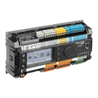
RS485-1 Bias and Termination Resistors
RS485-1 is equipped with a three-position slide switch which
can be used to switch its bias resistors OFF (position "MID" –
this is the default), ON (position "BIAS"), and ON with an
additional 150Ω termination resistor (position "END").
J1 J8
RS485-1
3-POSITION SLIDE SWITCH
END
BIAS
MID
Fig. 11. RS485-1 three-position slide switch
The recommended slide switch setting depends upon the
location and usage of the given EAGLE – see Fig. 12 and
Table 5; it also depends upon the selected communication
protocol (BACnet MS/TP, Panel Bus, or Modbus RTU Master
communication, respectively).
Table 5. Recommended slide switch settings
setting remarks
END
Controllers located on either end of bus should have
this setting.
BIAS
In small bus networks, a min. of one and a max. of
two controllers should have this setting.
MID
All other controllers (not set to "END" or "BIAS") on
bus should have this setting (which is the default).
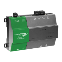
47 kOHM
47 kOHM
+5V
ISO
GND-1
RS485-1 (+)
RS485-1 (-)
25
26
MID (DEFAULT)
END
BIAS
MID
Fig. 12. RS485-1 three-position slide switch setting MID