EAGLE CONTROLLER – INSTALLATION & COMMISSIONING INSTRUCTIONS
9 EN1Z-0970GE51 R0918
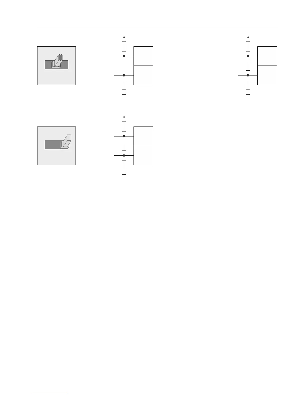
550 OHM
550 OHM
+5V
ISO
GND-1
RS485-1 (+)
RS485-1 (-)
25
26
BIAS
END
BIAS
MID
Fig. 13. RS485-1 three-position slide switch setting BIAS
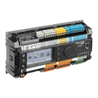
550 OHM
150 OHM
550 OHM
+5V
ISO
GND-1
RS485-1 (+)
RS485-1 (-)
25
26
END
END
BIAS
MID
Fig. 14. RS485-1 three-position slide switch setting END
NOTE: All terminals are protected (up to 24 Vac) against
short-circuiting and incorrect wiring – except when
the 3-position slide switch is set to "END," in which
case the terminals of the RS485-1 bus (24, 25, and
26) have no such protection. Higher voltages may
damage the device.
NOTE: According to BACnet standards, a minimum of one
and a maximum of two BACnet devices must have
its/their bias resistors switched ON. In the case of
the RS485-1 interface of the EAGLE, setting its
slide switch to either "BIAS" or "END" fulfills this
requirement.
RS485-2 Bias and Termination Resistors
The RS485-2 interface is not affected by the aforementioned
three-position slide switch. The 550Ω bias resistors and 130Ω
termination resistor of the RS485-2 are thus always ON.
550 OHM
130 OHM
550 OHM
+5V
GND-2
RS485-2 (+)
RS485-2 (-)
30
31
Fig. 15. RS485-2 bias and termination resistors
NOTE: GND-2 is internally connected with 24V-0
(terminal 1) and system GND (terminals 19+37)
RS485 Standard
According to the RS485 standard (TIA/EIA-485: "Electrical
Characteristics of Generators and Receivers for Use in
Balanced Digital Multipoint Systems"), only one driver com-
municating via an RS485 interface may transmit data at a
time. Further, according to U.L. requirements, each RS485
interface may be loaded with a max. of 32 unit loads. E.g.,
CentraLine devices have as little as ¼ unit load each, so that
up to 128 devices can be connected.
BACnet MS/TP connections to the RS485 interfaces must
comply with the aforementioned RS485 standard. Thus, it is
recommended that each end of every connection be equipped
with one termination resistor having a resistance equal to the
cable impedance (120 Ω / 0.25 – 0.5 W).
RS485 systems frequently lack a separate signal ground wire.
However, the laws of physics still require that a solid ground
connection be provided for in order to ensure error-free
communication between drivers and receivers – unless all of
the devices are electrically isolated and no earth grounding
exists.
IMPORTANT
In the case of new EAGLE controller installations, we
strongly recommend using a separate signal ground
wire. Doing otherwise may possibly lead to
unpredictable behavior if other electrically non-isolated
devices are connected and the potential difference is
too high.
In the case of the installation of EAGLE controllers in
already-existent RS485 two-wire systems (e.g., when
replacing PANTHER or LION controllers with EAGLE
controllers), not using a separate signal ground wire
will probably have no undesirable effects.
The cable length affects the baud rate. The following table
provides a few examples.