2.3 Assembly
2.3.1 General assembly
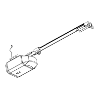
Open the packing carton and expose the XTrac components as depicted in
Figure.2
Orientate the Drive Rail (Figure.2-A) so that the Terminal Bracket (Figure.3-G)
faces towards the garage door
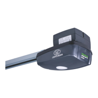
Locate the Drive Unit (Figure.2-C) and slide it into the Drive Rail and at the
same time insert the Drive Chain (Figure.1-B) into the Drive Unit. Slide the
Drive Unit at least 500mm in from the end of the Drive Rail
Note: Before attempting to insert the Drive Chain into the Drive Unit ensure
that the Drive Unit is disengaged (Refer Section.10)
Locate the Close Limit Prong (Figure.2-D) and slide it into the Drive Rail
Locate the Drive Rail Hanger (Figure.2-E) and slide it around the outside of the
Drive Rail. Make sure that the M8 dome head mounting bolts have been fitted
to the Drive Rail Hanger
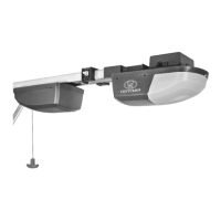
Insert the Control Box (Figure.3-F) into the Drive Rail
Insert the Drive Chain into the Tensioning Block (Figure.2A-F1) and then “Twist
and Lock” the Drive Chain into place (Figure.1A-F2)
Use a 12 mm socket wrench to tighten the Drive Chain Tensioner Bolt to the
point where the underside of the Bolt Head aligns with the Indicator Arrow on
the Terminal Bracket.(Figure.2B-G1)
Independent mounting of Control Box
With either of the methods A or B the Control Box may be mounted independently of
the Drive Rail.
An optional instruction sheet and fitting kit;
I. “FKA” is available for mounting the Control Box on the ceiling adjacent to the
Drive Rail.
II. “FKB” is available for mounting the Control Box on a side wall of the garage.
Page 7