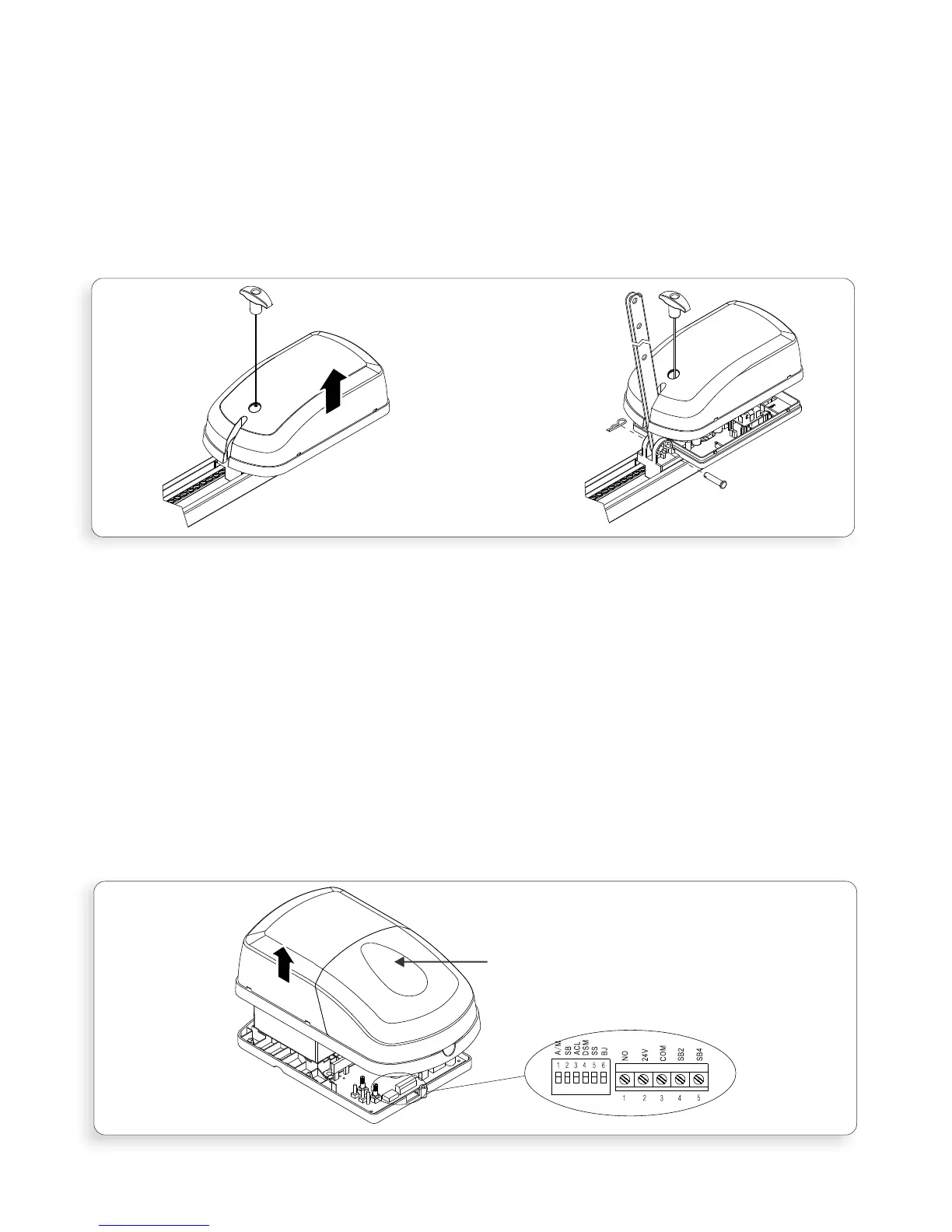
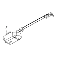
2.3.2 Attaching Straight Towing Arm
Remove the Drive Unit cover (Figure.4A) by pulling outwards and upwards, on
both sides, at the location marked by the arrow.
Insert the Straight Towing Arm through the slot in the cover (Figure.4B)
Note: use the end of the arm which has only one single hole.
Attach the arm to the Drive Unit using the short clevis pin and spring clip
provided (Figure.4B) and then replace the cover.
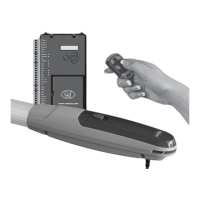
2.3.3 Options selection
Refer to Section.5.7 – Dipswitches and the sub section “functionality” and
select the required dipswitch functionality as required. Detailed explanation of
the different functions is provided under “Options and Features”
Section 5.1 – 5.19.
Refer to Section.5.1 – Accessory Connections to determine the external
accessory wiring that is required
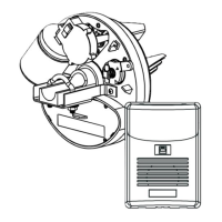
To access the Dipswitches and Accessory Connectors remove the Control Box
cover (Figure.5) by first removing the fixing screw, located under the light
cover and then pulling outwards and upwards, on both sides of the cover, at
the location marked by the arrow
Once functionality selection and wire connection has been completed replace
the cover
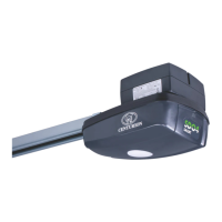
The XTrac is now fully assembled and ready for installation
Figure 4A
Page 9
Remove cover
fixing screw
under light
cover
Figure 4B
FIGURE 4. ATTACHING STRAIGHT TOWING ARM
FIGURE 5. ATTACHING STRAIGHT TOWING ARM