Page 23
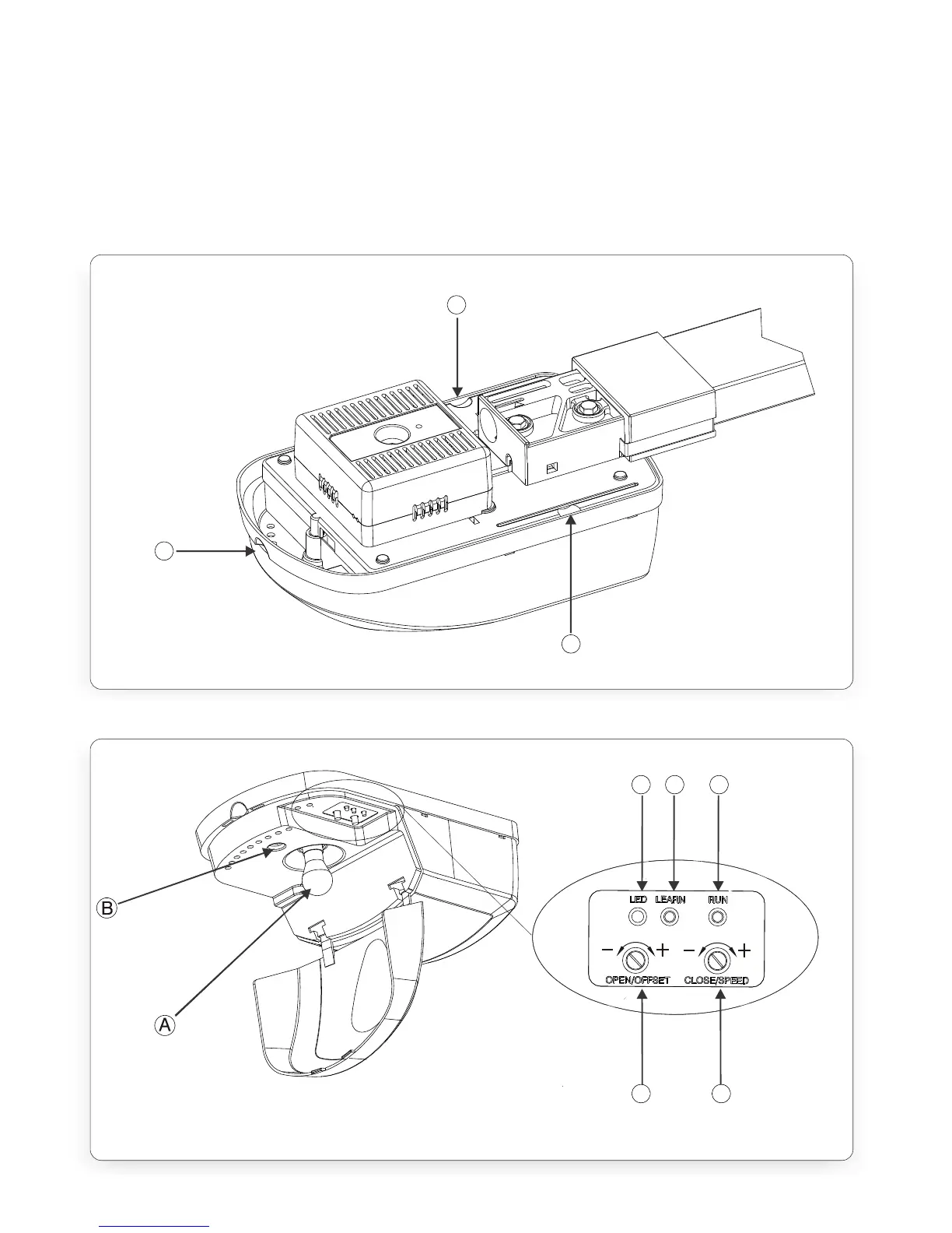
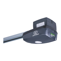
III. remove the Control Box cover Lock Screw point (Figure.19-B) Note: the Control
Box Cover can be removed once the head of the screw is protruding by
approximately 5mm.
IV. remove the Control Box cover by pulling first outwards and then downwards at
the finger recess points (Figure.18-B and C).
Replacement of all components is the reversal of removal
C
A
B
FIGURE 18. XTRAC CONTROL BOX
FIGURE 19. XTRAC CONTROL BOX
C D E
F G