C-net 2000 MULTI
34
11.2 Connections
GENERAL
Try to keep cable runs as short as possible to reduce the
risk of voltage drop and interference.
All cable runs should be kept at least 100mm (4) from
other cables carrying RF (Radio Frequency) or pulsed
signals.
If it is necessary to extend any of the data cables, the same
type of cable must be used and the screens must be
carried through.
SUPPLY
The supply must be 12 volt, from the switched side of a
Circuit Breaker and be fused, or protected, at 500 mA per
unit. For CAN Link runs totalling more than 10m, it is
advisable to supply power at both ends of the link, from
the same breaker.
TRANSDUCER & DATA INPUTS
NMEA 0183 instrument data can be connected to any
spare input of any unit in the system, (with the exception
of the Cetrek 3400 which cannot use NMEA 1 inputs).
Ensure only one source per input. The data is shared
throughout the system.
The Masthead Sensor 930387, the Speed/Depth interface
930346, Compass interfaces 930541 or 930543, GPS,
Navigator or Plotters all use this method.
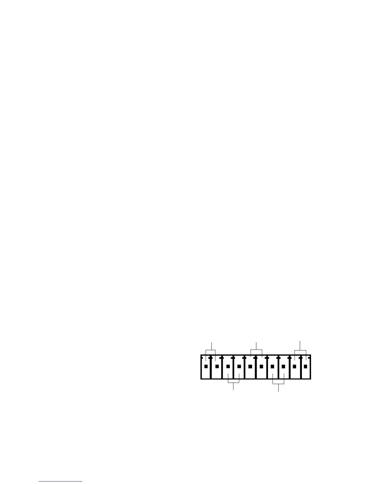
Wire them to the 10 way terminal block on the back.
12V supply
+ve, -ve
NMEA 1 input
(RX) +ve, -ve
+ve, -ve
NMEA 2 input (RX)
NMEA 3 input
(RX) +ve, -ve
-ve, +ve
NMEA output (TX)
pin 1
PL1 Pin-out
Details
BUS TERMINATION
The Bus Termination resistor must be fitted to the Power
lead connector of the unit at each end of the CAN link.
SCREEN CONNECTION
Where a Screen/Chassis/Ground connection is available,
(NOT SS-ve), connect all Screens to this point.