87
Regulation
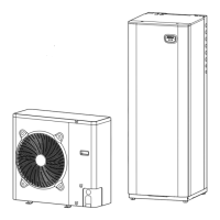
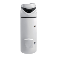
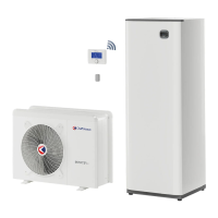
ARIANEXT COMPACT
Restoring operation
If the system shuts down, a code will appear on the system interface
display signalling the type of shutdown and the reason behind it.
To restore normal operation, follow the instructions provided on the
display or, if the error persists, contact an authorised Technical Service
Centre for assistance.
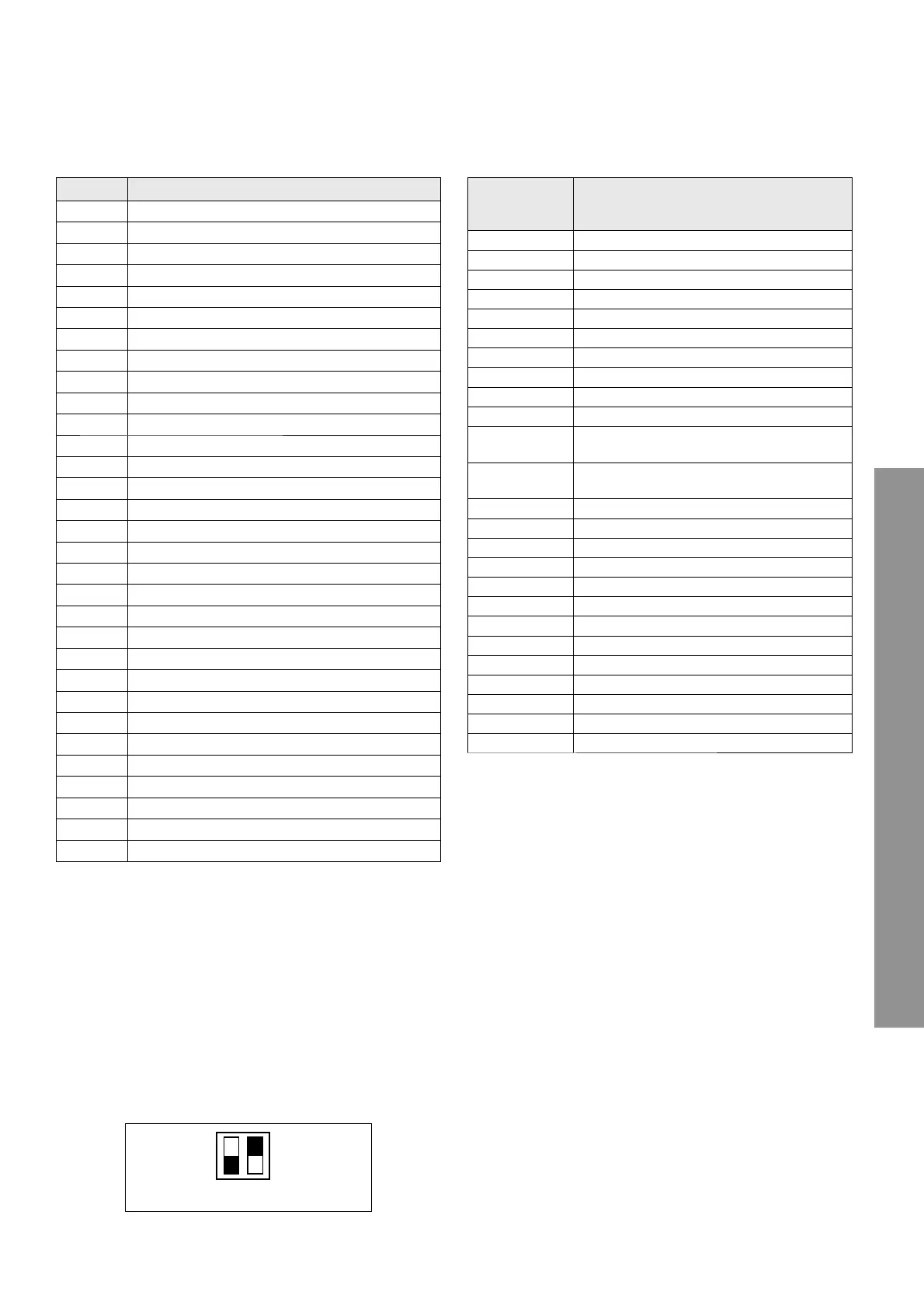
Table of error codes (PAC external unit)
In the case of an error on the external unit (PAC 939 error code), and
then read the parameter 17.10.1 refer to the following table to iden-
tify the cause of the error.
ERROR DESCRIPTION
1 14 Outdoor Sensor Damaged
4 20* Bus supply overload
7 01 Zone1 Send Probe Damaged
7 02 Zone2 Send Probe Damaged
7 03 Zone3 Send Probe Damaged (N/A)
7 11 Zone1 Return Probe Damaged
7 12 Zone2 Return Probe Damaged
7 13 Zone3 Return Probe Damaged (N/A)
7 22 Zone2 Overheat
7 23 Zone3 Overheat
9 02 System fl ow sensor damaged
9 03 System return sensor damaged
9 10 HP communication error (RS 485)
9 23 Heating Circuit pressure Error
9 24 Communication error (e-BUS 2)
9 33 Overheat (>90°C)
9 34 DHW Tank sensor damaged
9 35 Tank overtemperature (>85°C)
9 36 Floor Thermostat 1 error (ST1)
9 37 No circulation error
9 38 Anode Fault
939 HP error
9 40 Hydraulic scheme not defi ned
9 41 Night tariff contact not defi ned
9 42 Load shedding contact not defi ned
2 P2 Thermal cleanse not complete
2 P3 DHW boost: comfort setpoint not reached
2 P4 fi rst thermostat of resistance (auto)
2 P5 second thermostat of resistance (manual)
2 P6 Night tariff contact not present
2 P7 Precirculation Error
N/A = not applicable
(*) BUS power supply overload
A BUS power supply overload error may occur due to the connection
of three or more devices within the installed system. Devices which
may overload the BUS network include:
- Multizone module
- Solar pump assembly
- Module for instant production of domestic hot water
To avoid overloading the BUS power supply, set microswitch 1 on one
of the P.C.B.s inside the equipment connected to the system (except
the boiler) to OFF, as illustrated in the fi gure.
1
ON
OFF
2
microswitch
ERROR
(parameter
17.10.1)
DESCRIPTION
2 Safety Input
3 Enter water Temperature Sensor
4 Actual Refrigerant Temperature Sensor (TR)
5 Outdoor Air Sensor of GMC
6 Loss communication to NUI control
7 NUI control Room Sensor
9 Flow Switch error / Water Pump
10 EEProm Corrupt
11 User interface setting mismatch
12 4 Way valve error
13
Loss Communication to RS485 (system confi -
guration type 6)
14
Loss of Signal From inverter board or High Tem-
perature Release
15 Exit water Temperature Sensor (LWT)
16 Alarm Test
17 Inverter Air Sensor (TO)
18 G-Tr inverter short circuit protection
20 Compressor position Detection Circuit error
21 Inverter Current Sensor error
22 Heat Exchanger Sensors (TE) / (TS)
23 Discharge Temperature Sensor (TD)
24 Outdoor Fan motor error
26 Other unit error
27 Compressor Lock
28 Discharge Temperature error
29 Compressor Breakdown