operator.
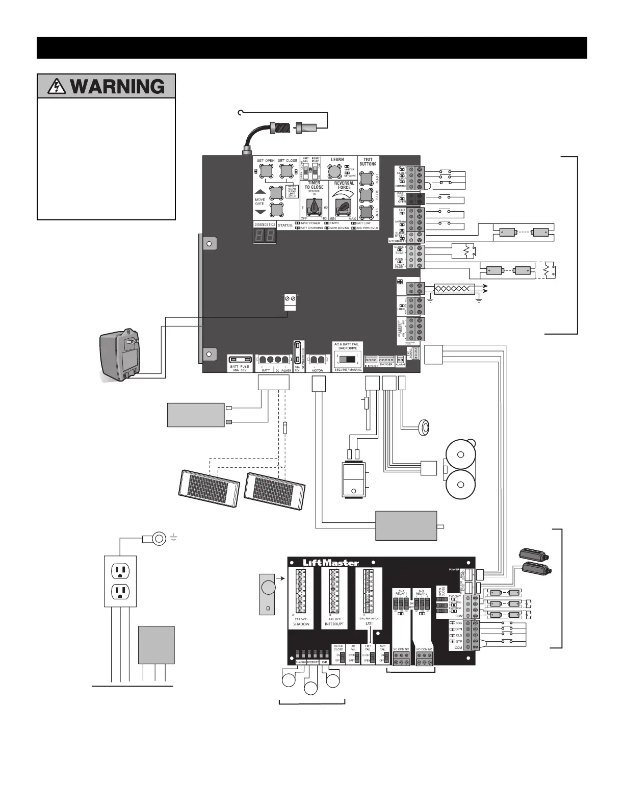
COM
LINK
B A
+
-
+
-
+
+
-
+
-
+
-
+
-
+
-
+
-
+
+
-
J25
Accessory Power
Outlets
L
N
GND
N
L
GND
Input Power Connection
Heater
Expansion Board (Optional)
Field Wiring
Field Wiring
Field Wiring
Wire Loop
Wire Loop
Wire Loop
Loop
Detector
12V 7AH Battery
Black
Red
Piezo Alarm
Encoder
White
White
Black
Red
Black
Black
Red
Run
Stop/Reset
Reset Switch
To Pin 1
To Pin 2
Product ID
Black
Red
Blocking
Diode
One, two, or three 10W Solar Panels wired
in parallel (30W maximum)
Red
Black
To J25
Transformer
Yellow
Blue
Black
Red
Primary/Secondary link
to other gate operator
Shielded
Twisted
Pair Cable
Ground the shield of the cable
to the chassis ground of each
operator.
Photoelectric Sensors
Field Wiring
Photoelectric Sensors
Coaxial Antenna Cable
Antenna
Control Board
N.C.
N.C.
Eye
Eye or
Edge
Edge
Edge
Wireless
Edge
Eye or
Edge
1/8 HP
12 Vdc Motor
OPEN and COM: Hard Open
(line-of-sight)
CLOSE and COM: Hard Close
(line-of-sight)
STOP and COM: Hard Stop
(line-of-sight)
EXIT: Soft Open (used for
exit probe,
telephone entry, external exit
loop detector, or any device
that would command the
gate to open)
 Loading...