A
anthonysnyderJul 29, 2025
What to do if my Chamberlain Garage Door Opener won't respond to any commands?
- SstephenhunterJul 29, 2025
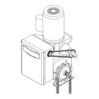
If your Chamberlain Garage Door Opener isn't responding, it could be due to: * Incorrect wiring of the operator control station. Ensure you're using the correct wiring. * A malfunctioning motor. Diagnose the motor to verify its condition.