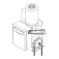
POWERHEAD ATTACHMENT
1. Position the track assembly on the frame of the
powerhead so that the motor side of operator is in back
(away from door ).
2. Loosely install two 3/8"-16 x 3/4" bolts and nuts in third
hole from the end of the track .
3. Align the track so that the bolts inserted in step 2 line up
with the L-Slots in the frame.
4. Connect the track to the powerhead by fastening two
3/8"-16 x 3/4" bolts and nuts through the frame and the
end holes in track. Tighten all four bolts to secure the
track to the powerhead.
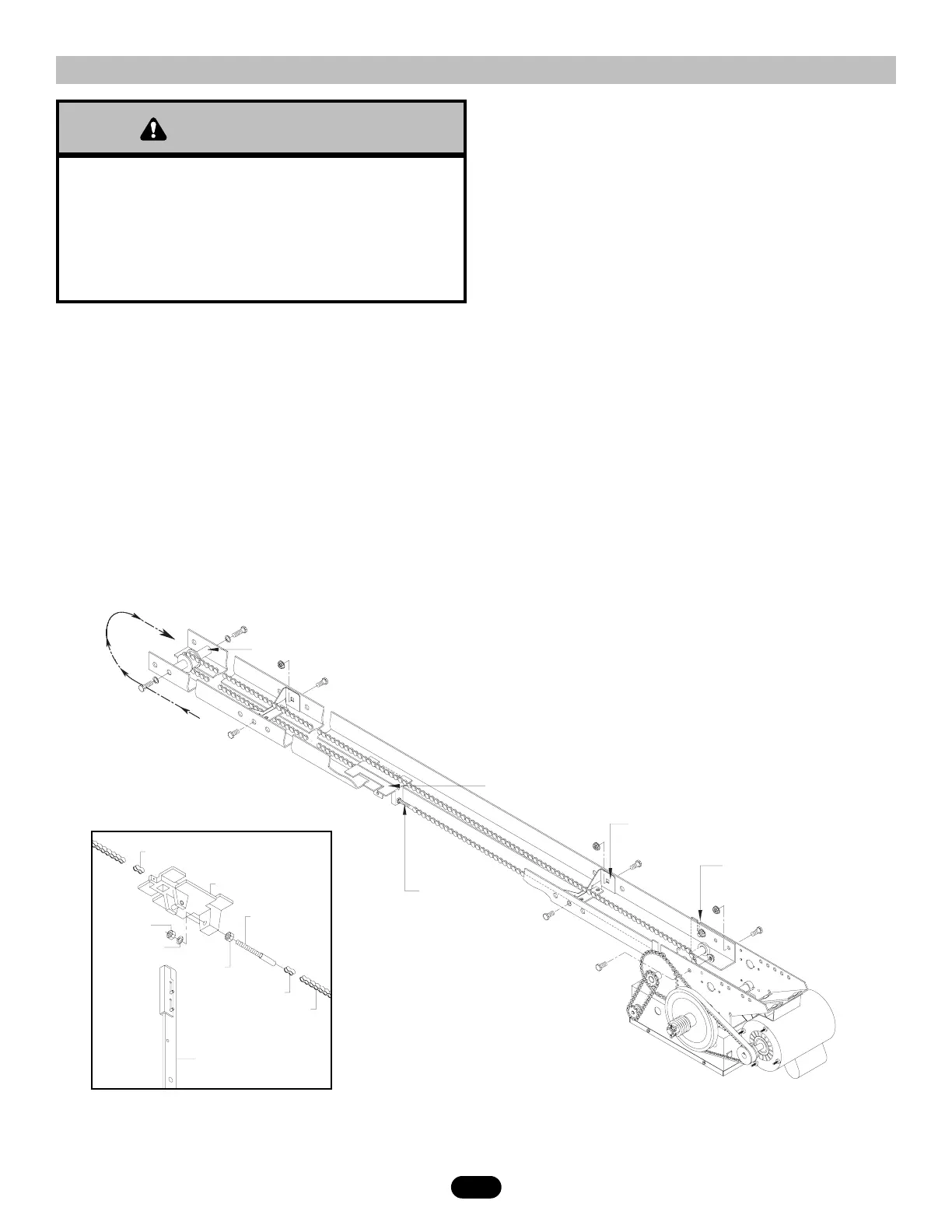
TROLLEY CARRIAGE / CHAIN ATTACHMENT
1. Attach the take-up bolt to the trolley carriage using
3/8-16" hex nuts and lock washer, as shown below.
2. Using one of the master links, attach the chain to the
other end of the trolley carriage. Reel the chain around
the front idler shaft, over the spacer brackets, back to
the drive shaft sprocket, and then to the take-up bolt on
the carriage.
3. Using the other master link, attach the chain to the
take-up bolt and tighten to the desired chain tension.
Chain Tension: With trolley positioned at either end of
the track, a properly adjusted chain will sag about 3" at the
mid-point. If necessary, remove links from the chain to
achieve proper adjustment.
KEEP DOOR BALANCED. STICKING OR BINDING DOORS
MUST BE REPAIRED. DOORS, DOOR SPRINGS, CABLES,
PULLEYS, BRACKETS AND THEIR HARDWARE MAY BE
UNDER EXTREME TENSION AND CAN CAUSE SERIOUS
PERSONAL INJURY OR DEATH. CALL A PROFESSIONAL
DOOR SERVICEMAN TO MOVE OR ADJUST DOOR SPRINGS
OR HARDWARE.
TRACK ASSEMBLY
1. Using the 3/8"-16 x 3/4" bolts and flange hex nuts
supplied, assemble the operator track by installing and
tightening the track spacer brackets. Position the
spacers evenly over the length of the track.
NOTE: The nylon pad on the spacer bracket should
face up.
2. Using (2) 3/8"-16 x 1" bolts and lock washers, install the
front idler assembly to the second set of holes of one
end of the track. Refer to the illustration below.
3. Slide the trolley carriage onto the track so that the
take-up bolt will be toward the operator.