Multi-Channel Sync Hipot Tester 19020/19020-4/19021/19022/19022-4
Quick Start Guide
(4) Position 4 is the message line that is varied with the setting items of each
parameter. It prompts the parameter setting message and range.
Please follow the model to set the output channel, for
instance, the 19020 can set the output channel to
CH1~CH10 while the 19020-4 can only set the channel
to CH1~CH4. The message line on the test screen will
show ”Module Fail” if set otherwise and the test is
unable to start.
3.3.2 Connecting the UUT
First ensure there is no voltage output and the DANGER LED is off. Connect the
low potential test cable (black) to the Tester RTN/LOW terminal. Short-circuit the
test cable and high voltage output terminal and ensure there is no high voltage
output. Next, plug in the high voltage test cable (red or white) to high voltage
output terminal. Then connect the low potential test cable to UUT and the high
potential test cable to UUT.
3.3.3 Test Procedure
(1) Connect the UUT properly following the connection method.
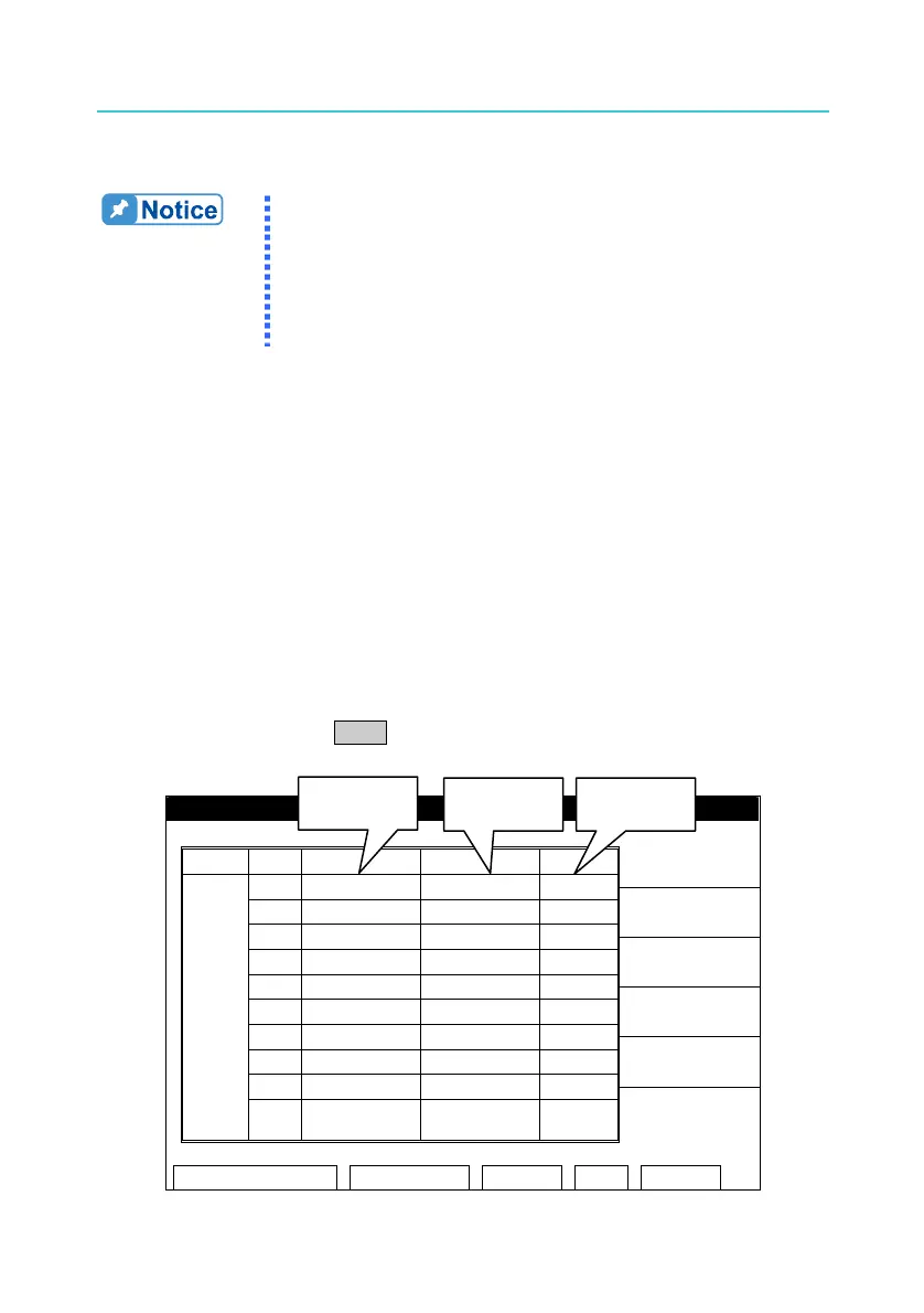
(2) In any screen, press TEST and it is ready as shown below:
TEST – 1/2
MODE CH SOURCE LIMIT RES. RECALL
01 0.050kV 0.500mA
Position 1
Position 2 Position 3
02 0.050kV 0.500mA OFFSET
03 0.050kV 0.500mA
04 0.050kV 0.500mA GET Cs
05 0.050kV 0.500mA
06 0.050kV 0.500mA
07 0.050kV 0.500mA
08 0.050kV 0.500mA CLEAR
09 0.050kV 0.500mA
SLAVE
AC
10 0.050kV 0.500mA
1 2 3 4 5 6 7 8 9
STANDBY REMOTE LOCK CORR ERROR
14
 Loading...


