Programmable DC Power Supply 62000P Series Operating & Programming Manual
NOTE
1. Minimum output voltage <0.15% of rate voltage.
2. Minimum output current <0.2% of rate current.
3. 95-250Vac with rated load.
4. For 0-100% load step with nominal line voltage.
5. Verified by scope with BNC cable and 50 (Ohm) termination.
6. At rated current with 10m ohm load.
7. Typical efficiency at nominal input voltage (230V) under maximum output voltage.
8. Maximum drift over 8 hours with constant line-in, loading and temperature after 30
minutes warm-up.
9. Change in output per °C in ambient temperature with constant line and load.
10. This specification is also referred to as Step Load Response. For a load step change
from10% variation. (loading slew rate is 0.1A/us for rise and fall)
All specifications are subject to change without prior notice.
1.3.1 Other Specifications
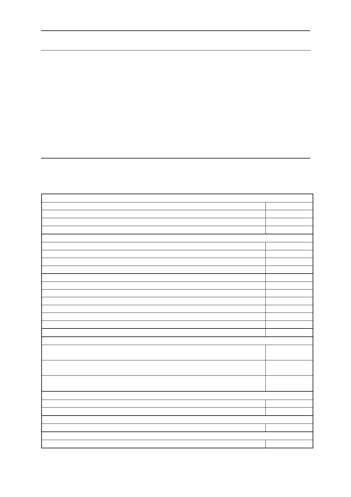
Programming &Measurement Resolution
Voltage (Front Panel, Remote Interface) 0.003% of Vmax
Current (Front Panel, Remote Interface) 0.002% of Imax
Voltage (Analog Programming Interface) 0.04% of Vmax
Current (Analog Programming Interface) 0.04% of Imax
Programming Accuracy
Voltage Programming (Front Panel and Remote Interface) 0.1% of Vmax
Voltage Programming (Analog Programming Interface) 0.2% of Vmax
Current Programming (Front Panel and Remote Interface) 0.3% of Imax
Current Programming (Analog Programming Interface) 0.3% of Imax
Programming Response Time
Rise Time: For a programmed 5 to 95% step of rated voltage. (Full Load) 100ms
Rise Time: For a programmed 5 to 95% step of rated voltage. (No Load) 100ms
Fall Time: For a programmed 95% to 5 step of rated voltage. (Full Load) 60ms
Fall Time: For a programmed 95% to 5 step of rated voltage. (No Load) 840mS MAX
Vout setting (GPIB send command to DC Power Supply receiver) 20ms
?Volt, ? Current (under GPIB command using Fetch) 25ms
?Volt, ? Current (under GPIB command using Measure) 70ms
Analog Programming Interface
Voltage and Current Programming inputs
0~10Vdc or
0~5Vdc of F.S.
Voltage and Current monitor
0~10Vdc or
0~5Vdc of F.S.
Isolation: Maximum working voltage of any analog programming signal with respect
to chassis potential.
70Vdc
Auxiliary Power Supply
Output Voltage 12Vdc
Maximum current source capability 10mA
Remote Inhibit Function
Use to disable the output of DC Power Supply; Active Low. TTL
DC-ON Output Signal
Indicate the output status, Active High. TTL
1-4
 Loading...


