Programmable DC Power Supply 62000P Series Operating & Programming Manual
3.3.1.3 APG
Analog Programming interface (APG) uses analog signal to control the output. This option
decides whether or which APG control function is in use, and no matter what option is
selected the measurement functions are available.
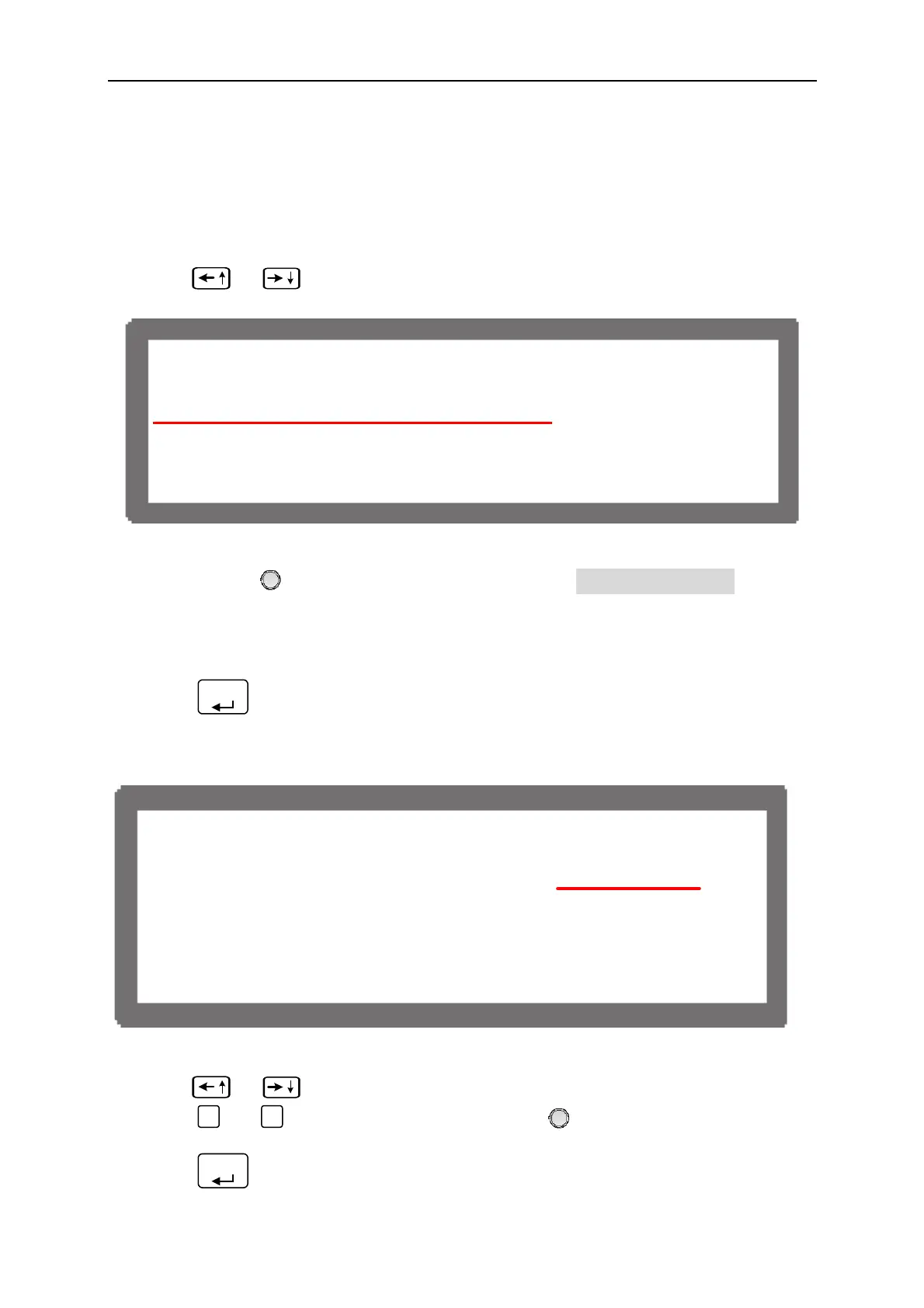
1. Use “
”, “
” keys to move the cursor to the column to be set.
[ S Y S T E M S E T U P ]
G P I B A D D R = 1
R S - 2 3 2 B A U D R A T E = 9 6 0 0
A P G = N O N E
B A C K L I G H T = H I G H
B U Z Z E R = O N
P O W E R O N S T A T U S = D E F A U L T
Figure 3-6
2. Use “Rotary” (
) to set the mode. APG has 4 options: NONE / V / I / V&I, where:
NONE: It indicates not using the programming function for voltage and current.
V: It indicates using voltage programming but not current programming function.
I: It indicates using current programming but not voltage programming function.
V&I: It indicates using both voltage and current programming function.
3. Press “
ENTER
” to confirm.
4. A reference potential option will prompt at the right for selection when the APG function
is enabled.
[ S Y S T E M S E T U P ]
G P I B A D D R = 1
R S - 2 3 2 B A U D R A T E = 9 6 0 0
A P G = V Vref(V ) =5
B A C K L I G H T = H I G H
B U Z Z E R = O N
P O W E R O N S T A T U S = D E F A U L T
Figure 3-7
5. Use “
”, “
” keys to move the cursor to the column to be set.
6. Press “
0
” or “
1
” to set the value, or use “Rotary” (
) knob to select the control
voltage range.
7. Press “
ENTER
” to confirm.
3-6
 Loading...


