21798-01-EN Rev. 04 Page 20
4.5.1.2 Panel Mounting
The display has four M6-1.0 studs for panel mounting. Panel cutout
dimensions and a cutout template are provided in Appendix D at the end of
this manual.
4.6 Battery Charger
The battery charger (Figure 16) should be mounted inside the truck cab where
it is out of the way but accessible by the driver. The charger is supplied with a
12VDC plug for connecting to the truck power outlet.
The SMARThatch System is supplied with two batteries. While one is being
used in the sensor the other may be stored in the battery charger, so it is
always charged and ready for use.
Figure 16: Battery Charger
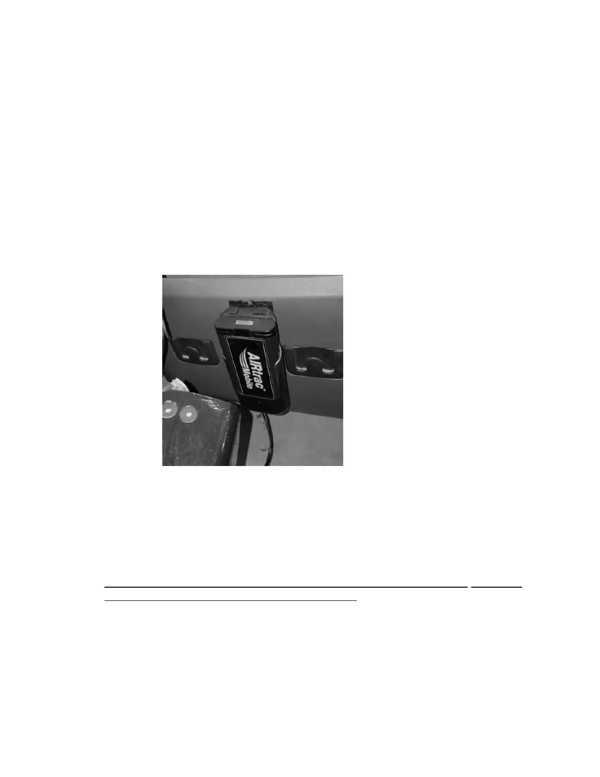
4.7 Telematics Module Installation
Determine a location for the telematics module inside the truck cab.
The mounting location must allow the 1 ft (0.3 m) telematics cable to be spliced
to the free end of both the receiver and display cables.
Prior to mounting the receiver module, display and telematics module, verify the
free end all cables can reach a common location. Also, use the form in
APPENDIX B - Installation Record to record the telematics module serial number
located on the back of the module (Figure 17) and truck identification number for
each installed SMARThatch system.
Use self-tapping screws or equivalent to hold the telematics module securely
in place (screws not provided).