21798-01-EN Rev. 04 Page 28
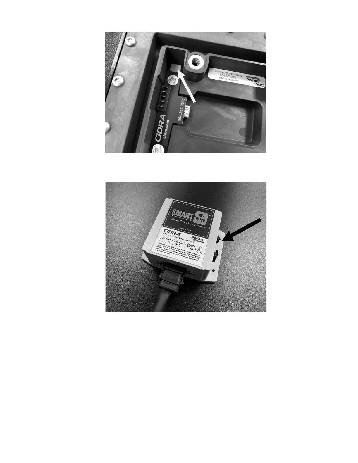
Figure 22: Sensor Pairing Button and LED inside battery compartment
(battery removed for clarity, but must be installed during pairing)
4.9.2 Telematics Configuration and Activation
The telematics module must be configured so it is uniquely associated with the
truck that it is installed, based on the serial number and truck identification
recorded during installation (Section 4.7).
Contact CiDRA Concrete Customer Support (Section 1.4) for assistance with
configuration and activation of the telematics module.
Figure 23: Receiver Module Pairing Button and LED