Before opening the unit, disconnect the telephone-network cables to avoid contact with telephone-network
voltages. Statement 1041.
Warning
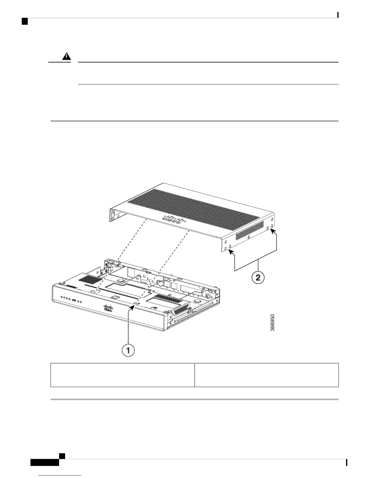
Remove the Cover
To remove the cover, perform the following steps:
Step 1 Disconnect the power supply before you perform any module replacement.
Step 2 Confirm the router is turned off and disconnected from the power supply.
Step 3 Place the chassis on a flat surface.Remove the fourteen cover screws on the two sides of the router cover.
Step 4 Slide the cover from bezel side to I/O side until it stops. Remove all screws on both sides of the router; there are seven
screws on each side.
Step 5 Pull the cover to disengage the slots along the front (bezel) edge of the chassis, as shown in this figure.
Slots
Screw holes (7 numbers on each side)
1
2
Hardware Installation Guide for the Cisco 1000 Series Integrated Services Router
42
Install and Upgrade Internal Modules and FRUs
Remove the Cover