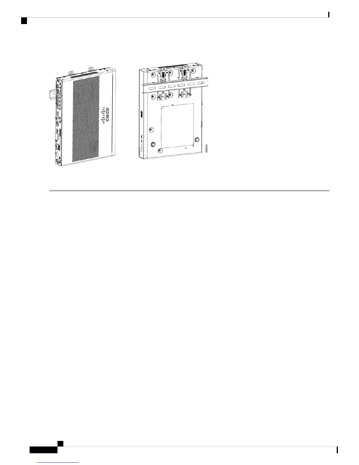
Figure 21: DIN Rail Brackets and Mount
Do not over-torque the screws. The recommended torque is 8 to 10 inch-lbf (0.9 to 1.1 N-m).
Note
Chassis Grounding
After you set up the router, connect the chassis to a reliable earth ground; the ground wire must be installed
in accordance with local electrical safety standards. For safety information on grounding the chassis, refer to
the chassis ground connection procedures.
1. For grounding the chassis, use a copper wire of size 14 AWG (2 mm²) and the ground lug. These are not
a part of the accessory kit.
2. Use the UNC 6-32 screws, which have a length of about 0.25 inches.
To install the ground connection for your router, perform these steps:
1. Strip one end of the ground wire to the length required for the ground lug or terminal.
• For the ground lug—approximately 0.75 inch (20 mm)
• For user-provided ring terminal—as required
2. Crimp the ground wire to the ground lug or ring terminal, using a crimp tool of the appropriate size.
3. Attach the ground lug or ring terminal to the chassis as shown in Figure. The screw for the ground lug is
provided. Tighten the screw; the recommended torque is 8 to 10 inch-lbf (0.9 to 1.1 N-m).
Hardware Installation Guide for the Cisco 1000 Series Integrated Services Router
32
Install and Connect the Router
Chassis Grounding