Step 3 Installer to disconnect all cables connected to the system.
Step 4 Place the chassis on a flat surface.
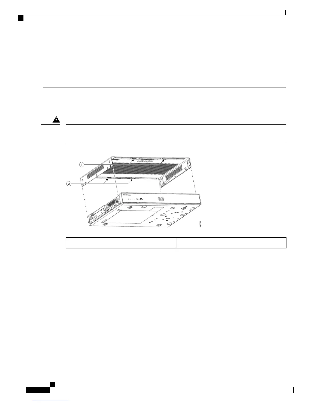
Step 5 Remove the 14x cover screws on the two sides of the router cover. See figure.
Step 6 Slide the cover from bezel side to I/O side until it stops.
Step 7 Pull the cover vertically to disengage from the chassis.
Replace the Cover
To replace the cover, do these steps:
The covers are an integral part of the safety design of the product. Do not operate the unit without the covers
installed. Statement 1077.
Warning
Replace the 14 screws on either side of the cover.1 and 2
Hardware Installation Guide for the Cisco 1000 Series Integrated Services Router
46
Install and Upgrade Internal Modules and FRUs
Replace the Cover