2-27
Catalyst 3750 Switch Hardware Installation Guide
OL-6336-10
Chapter 2 Switch Installation
Installing the Switch
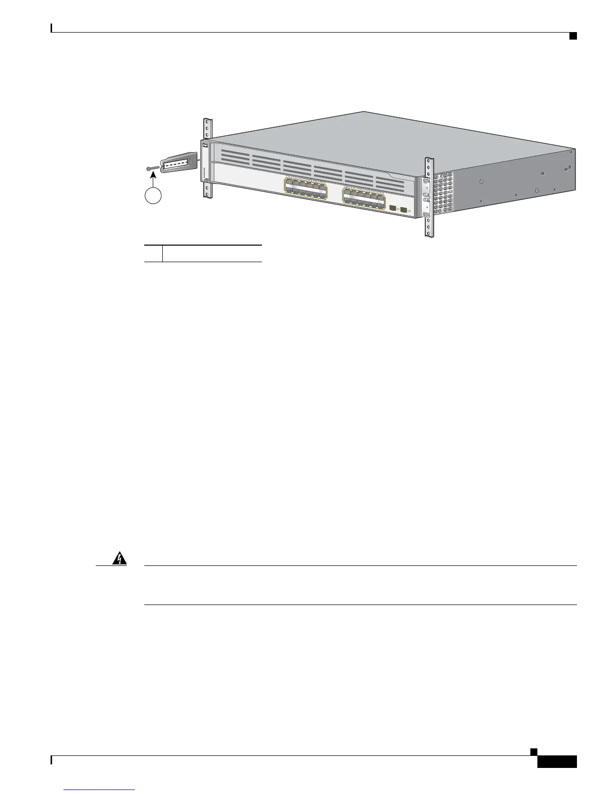
Figure 2-40 Attaching the Cable Guide on the Catalyst 3750 Integrated Wireless LAN Controller
Switches
Wall-Mounting
These switches wall-mount only with the front panel facing up:
• Catalyst 3750-24FS, Catalyst 3750V2-24FS
• Catalyst 3750-24TS, 3750-48TS, 3750-24PS, 3750-48PS
• Catalyst 3750G-12S, 3750G-12S-SD
• Catalyst 3750G-24T, 3750G-24TS, 3750G-24TS-1U
• Catalyst 3750G-24PS, 3750G-48PS
• Catalyst 3750G-16TD
These switches wall-mount with the front panel facing up or down:
• Catalyst 3750V2-24TS, 3750V2-48TS
• Catalyst 3750V2-24PS, 3750V2-48PS
These switches do not support wall-mounting. Do not wall-mount these switches:
• Catalyst 3750G-24WS-S25
• Catalyst 3750G-24WS-S50
The illustrations in this section show the Catalyst 3750G-24TS switch as an example.
Warning
Read the wall-mounting instructions carefully before beginning installation. Failure to use the
correct hardware or to follow the correct procedures could result in a hazardous situation to people
and damage to the system.
Statement 378
To install the switch on a wall, follow the instructions in these procedures:
• Attaching the Brackets to the Switch for Wall-Mounting, page 2-28
• Attaching the RPS Connector Cover, page 2-28
• Mounting the Switch on a Wall, page 2-29
1 Cable guide screws
Catalyst 3750G
SERIES
PoE-24
Wireless L
AN Controller
SYST
RPS
MASTR
STAT
DUPLX
SPEED
STACK
PoE
1X
2X
11X
12X
1
2
3
4
5
6
7
8
9
10
11
12
13X
14X
23X
24X
13
14
15
16
17
18
19
20
21
22
23
24
25
26
1
141735