EasyManuals Logo

Cisco 3750G - Catalyst Integrated Wireless LAN Controller User Manual

Cisco 3750G - Catalyst Integrated Wireless LAN Controller
1204 pages
To Next Page IconTo Next Page
To Previous Page IconTo Previous Page
Page #795 background imageLoading...
Page #795 background image
34-3
Catalyst 3750 Switch Software Configuration Guide
OL-8550-02
Chapter 34 Configuring EtherChannels and Link-State Tracking
Understanding EtherChannels
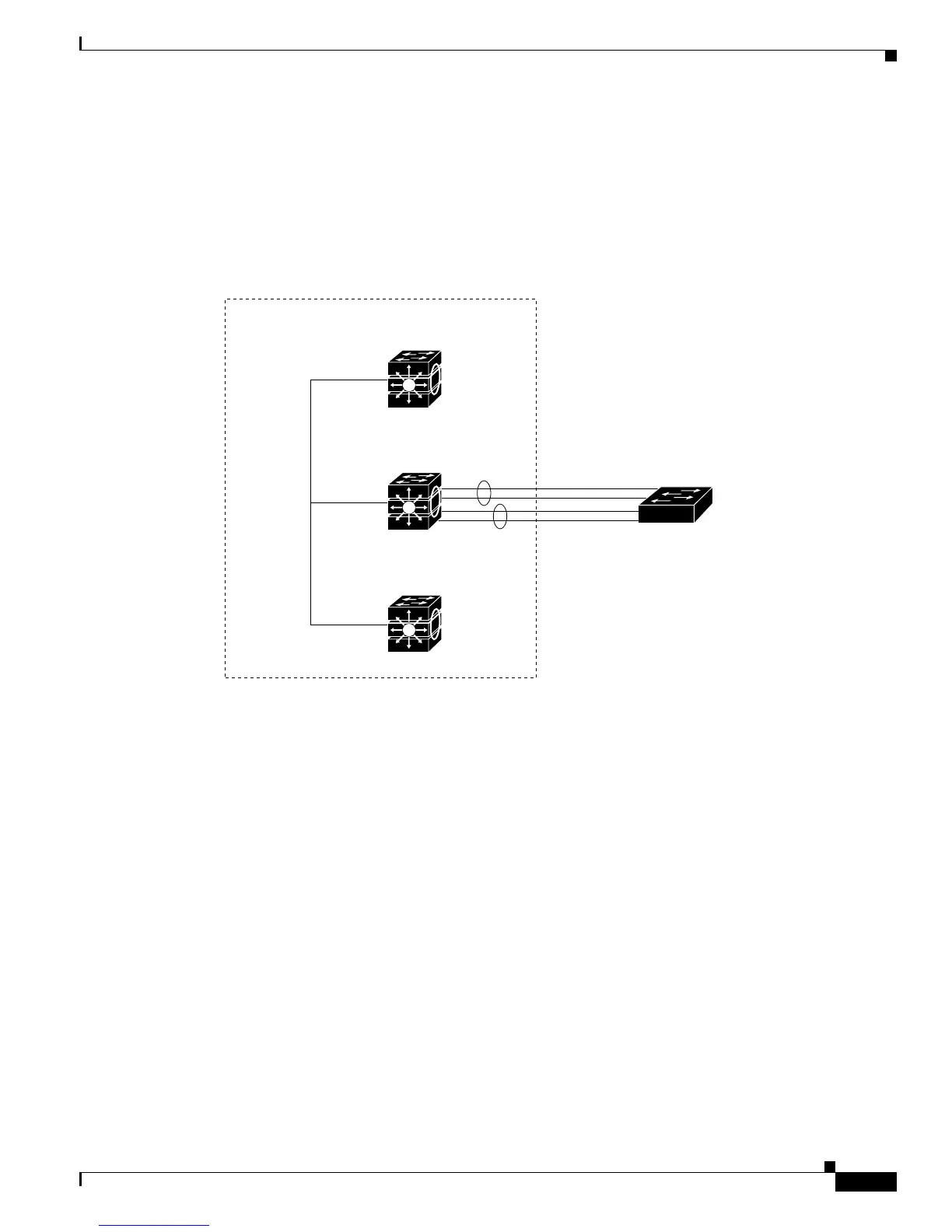
You can create an EtherChannel on a standalone switch, on a single switch in the stack, or on multiple
switches in the stack (known as cross-stack EtherChannel). See Figure 34-2 and Figure 34-3.
If a link within an EtherChannel fails, traffic previously carried over that failed link moves to the
remaining links within the EtherChannel. If traps are enabled on the switch, a trap is sent for a failure
that identifies the switch, the EtherChannel, and the failed link. Inbound broadcast and multicast packets
on one link in an EtherChannel are blocked from returning on any other link of the EtherChannel.
Figure 34-2 Single-Switch EtherChannel
Switch 1
Catalyst 3750 switch stack
Switch 2
Channel
group 1
Channel
group 2
StackWise
port
connections
Switch 3
Switch A
86492

Table of Contents

Questions and Answers:

Question and Answer IconNeed help?

Do you have a question about the Cisco 3750G - Catalyst Integrated Wireless LAN Controller and is the answer not in the manual?

Cisco 3750G - Catalyst Integrated Wireless LAN Controller Specifications

General IconGeneral
Switching Capacity32 Gbps
RAM128 MB
Flash Memory32 MB
Power DeviceInternal power supply
Ports48 x 10/100/1000 + 4 x SFP
Performance38.7 Mpps
Wireless LAN Controller Capacity50
StackingYes
FeaturesVLAN support, QoS
Compliant StandardsIEEE 802.3, IEEE 802.3u, IEEE 802.3ab, IEEE 802.3z
Operating Humidity10% to 85% non-condensing
Power over Ethernet (PoE)Yes (optional)

Related product manuals