35-66
Catalyst 3750 Switch Software Configuration Guide
OL-8550-02
Chapter 35 Configuring IP Unicast Routing
Configuring Multi-VRF CE
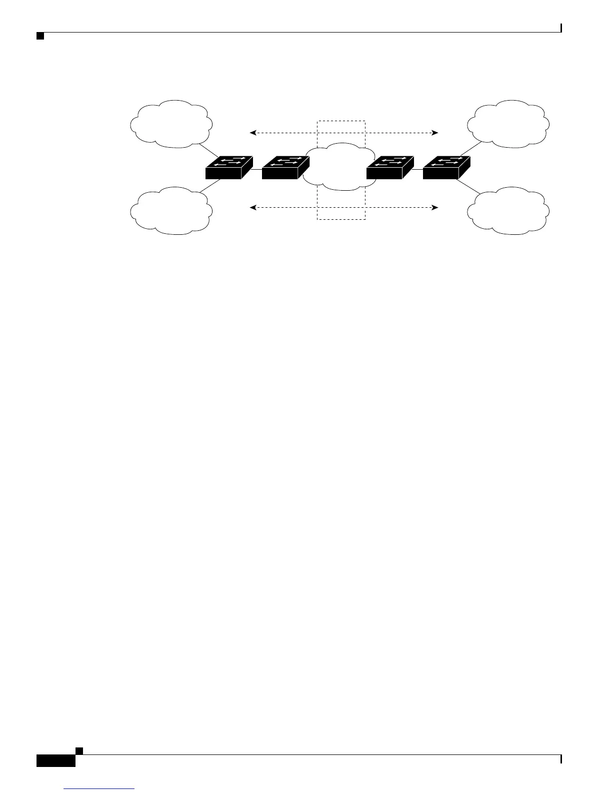
Figure 35-6 Catalyst 3750 Switches Acting as Multiple Virtual CEs
When the CE switch receives a command to add a Layer 3 interface to a VRF, it sets up the appropriate
mapping between the VLAN ID and the policy label (PL) in multi-VRF-CE-related data structures and
adds the VLAN ID and PL to the VLAN database.
When multi-VRF CE is configured, the Layer 3 forwarding table is conceptually partitioned into two
sections:
• The multi-VRF CE routing section contains the routes from different VPNs.
• The global routing section contains routes to non-VPN networks, such as the Internet.
VLAN IDs from different VRFs are mapped into different policy labels, which are used to distinguish
the VRFs during processing. For each new VPN route learned, the Layer 3 setup function retrieves the
policy label by using the VLAN ID of the ingress port and inserts the policy label and new route to the
multi-VRF CE routing section. If the packet is received from a routed port, the port internal VLAN ID
number is used; if the packet is received from an SVI, the VLAN number is used.
This is the packet-forwarding process in a multi-VRF-CE-enabled network:
• When the switch receives a packet from a VPN, the switch looks up the routing table based on the
input policy label number. When a route is found, the switch forwards the packet to the PE.
• When the ingress PE receives a packet from the CE, it performs a VRF lookup. When a route is
found, the router adds a corresponding MPLS label to the packet and sends it to the MPLS network.
• When an egress PE receives a packet from the network, it strips the label and uses the label to
identify the correct VPN routing table. Then it performs the normal route lookup. When a route is
found, it forwards the packet to the correct adjacency.
• When a CE receives a packet from an egress PE, it uses the input policy label to look up the correct
VPN routing table. If a route is found, it forwards the packet within the VPN.
To configure VRF, you create a VRF table and specify the Layer 3 interface associated with the VRF.
Then configure the routing protocols in the VPN and between the CE and the PE. BGP is the preferred
routing protocol used to distribute VPN routing information across the provider’s backbone. The
multi-VRF CE network has three major components:
• VPN route target communities—lists of all other members of a VPN community. You need to
configure VPN route targets for each VPN community member.
• Multiprotocol BGP peering of VPN community PE routers—propagates VRF reachability
information to all members of a VPN community. You need to configure BGP peering in all PE
routers within a VPN community.
VPN 1
VPN 2
VPN 1
VPN 2
CE2PE1 PE2
Service
provider
CE1
CE = Customer-edge device
PE = Provider-edge device
101385