40-20
Catalyst 3750 Switch Software Configuration Guide
OL-8550-02
Chapter 40 Configuring IP Multicast Routing
Configuring IP Multicast Routing
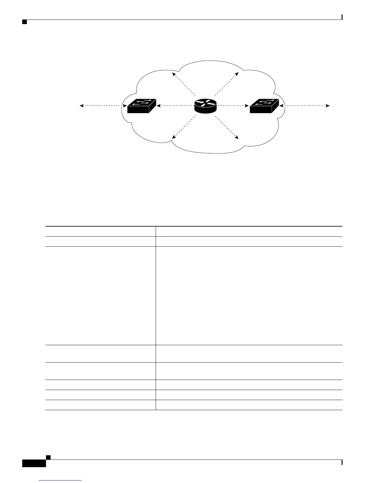
Figure 40-3 Constraining PIMv2 BSR Messages
Defining the IP Multicast Boundary
You define a multicast boundary to prevent Auto-RP messages from entering the PIM domain. You
create an access list to deny packets destined for 224.0.1.39 and 224.0.1.40, which carry Auto-RP
information.
Beginning in privileged EXEC mode, follow these steps to define a multicast boundary. This procedure
is optional.
To remove the boundary, use the no ip multicast boundary interface configuration command.
101243
PIMv2 sparse-mode
network
BSR
BSR
messages
Neighboring
PIMv2 domain
Neighboring
PIMv2 domain
Configure the
ip pim bsr-border
command on
this interface.
Configure the
ip pim bsr-border
command on
this interface.
BSR
messages
Layer 3
switch
Layer 3
switch
Command Purpose
Step 1
configure terminal Enter global configuration mode.
Step 2
access-list access-list-number deny
source [source-wildcard]
Create a standard access list, repeating the command as many times as
necessary.
• For access-list-number, the range is 1 to 99.
• The deny keyword denies access if the conditions are matched.
• For source, enter multicast addresses 224.0.1.39 and 224.0.1.40,
which carry Auto-RP information.
• (Optional) For source-wildcard, enter the wildcard bits in dotted
decimal notation to be applied to the source. Place ones in the bit
positions that you want to ignore.
Recall that the access list is always terminated by an implicit deny
statement for everything.
Step 3
interface interface-id Specify the interface to be configured, and enter interface configuration
mode.
Step 4
ip multicast boundary
access-list-number
Configure the boundary, specifying the access list you created in Step 2.
Step 5
end Return to privileged EXEC mode.
Step 6
show running-config Verify your entries.
Step 7
copy running-config startup-config (Optional) Save your entries in the configuration file.