40-25
Catalyst 3750 Switch Software Configuration Guide
OL-8550-02
Chapter 40 Configuring IP Multicast Routing
Configuring Advanced PIM Features
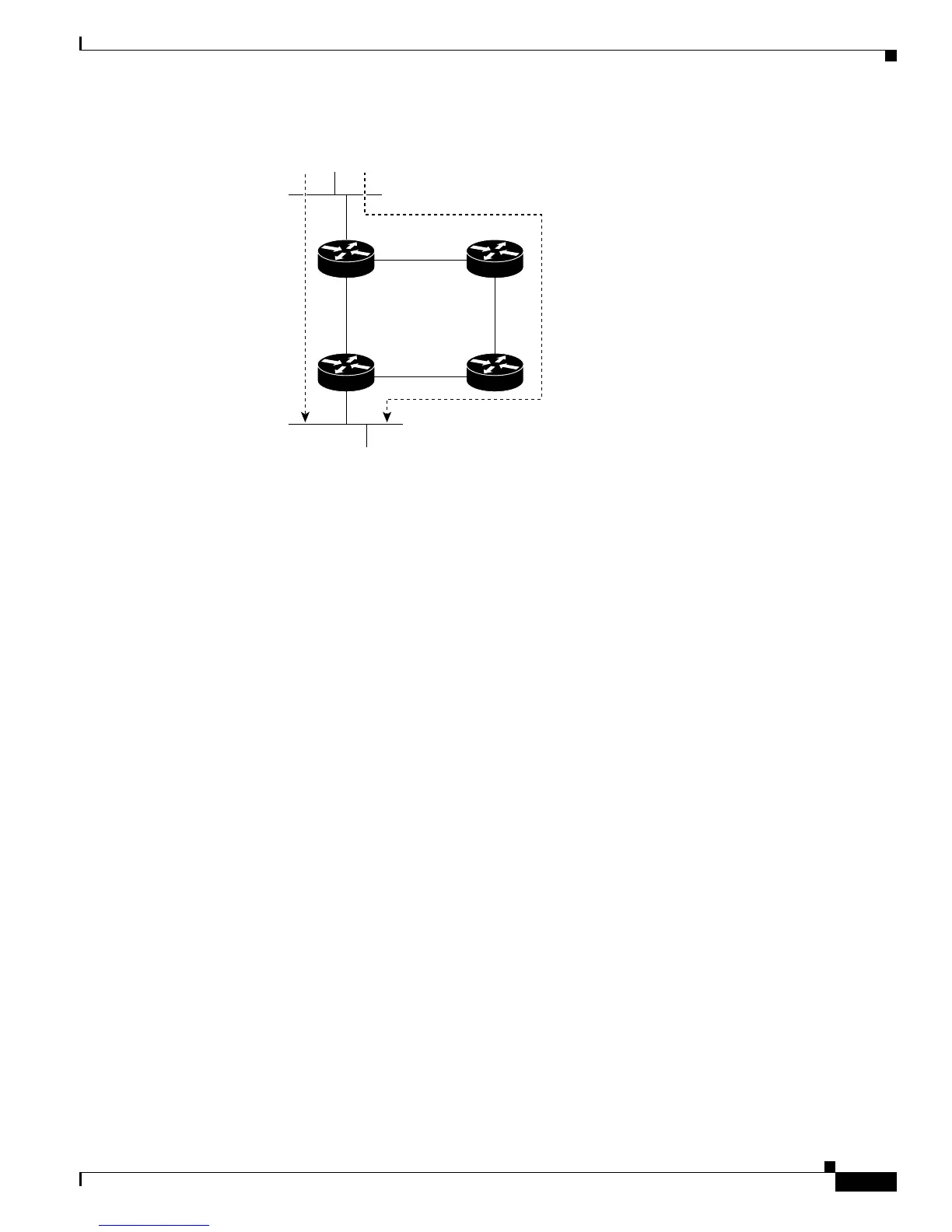
Figure 40-4 Shared Tree and Source Tree (Shortest-Path Tree)
If the data rate warrants, leaf routers (routers without any downstream connections) on the shared tree
can use the data distribution tree rooted at the source. This type of distribution tree is called a
shortest-path tree or source tree. By default, the software switches to a source tree upon receiving the
first data packet from a source.
This process describes the move from a shared tree to a source tree:
1. A receiver joins a group; leaf Router C sends a join message toward the RP.
2. The RP puts a link to Router C in its outgoing interface list.
3. A source sends data; Router A encapsulates the data in a register message and sends it to the RP.
4. The RP forwards the data down the shared tree to Router C and sends a join message toward the
source. At this point, data might arrive twice at Router C, once encapsulated and once natively.
5. When data arrives natively (unencapsulated) at the RP, it sends a register-stop message to Router A.
6. By default, reception of the first data packet prompts Router C to send a join message toward the
source.
7. When Router C receives data on (S,G), it sends a prune message for the source up the shared tree.
8. The RP deletes the link to Router C from the outgoing interface of (S,G). The RP triggers a prune
message toward the source.
Join and prune messages are sent for sources and RPs. They are sent hop-by-hop and are processed by
each PIM device along the path to the source or RP. Register and register-stop messages are not sent
hop-by-hop. They are sent by the designated router that is directly connected to a source and are received
by the RP for the group.
Multiple sources sending to groups use the shared tree.
You can configure the PIM device to stay on the shared tree. For more information, see the “Delaying
the Use of PIM Shortest-Path Tree” section on page 40-26.
Router A
Source
Receiver
Router C
RP
Router B
Shared tree
from RP
Source tree
(shortest
path tree)
44967