27-4
Software Configuration Guide—Release 12.2(25)EW
OL-6696-01
Chapter 27 Understanding and Configuring VTP
Overview of VTP
For VTP pruning to be effective, all devices in the management domain must either support VTP pruning
or, on devices that do not support VTP pruning, you must manually configure the VLANs allowed on
trunks.
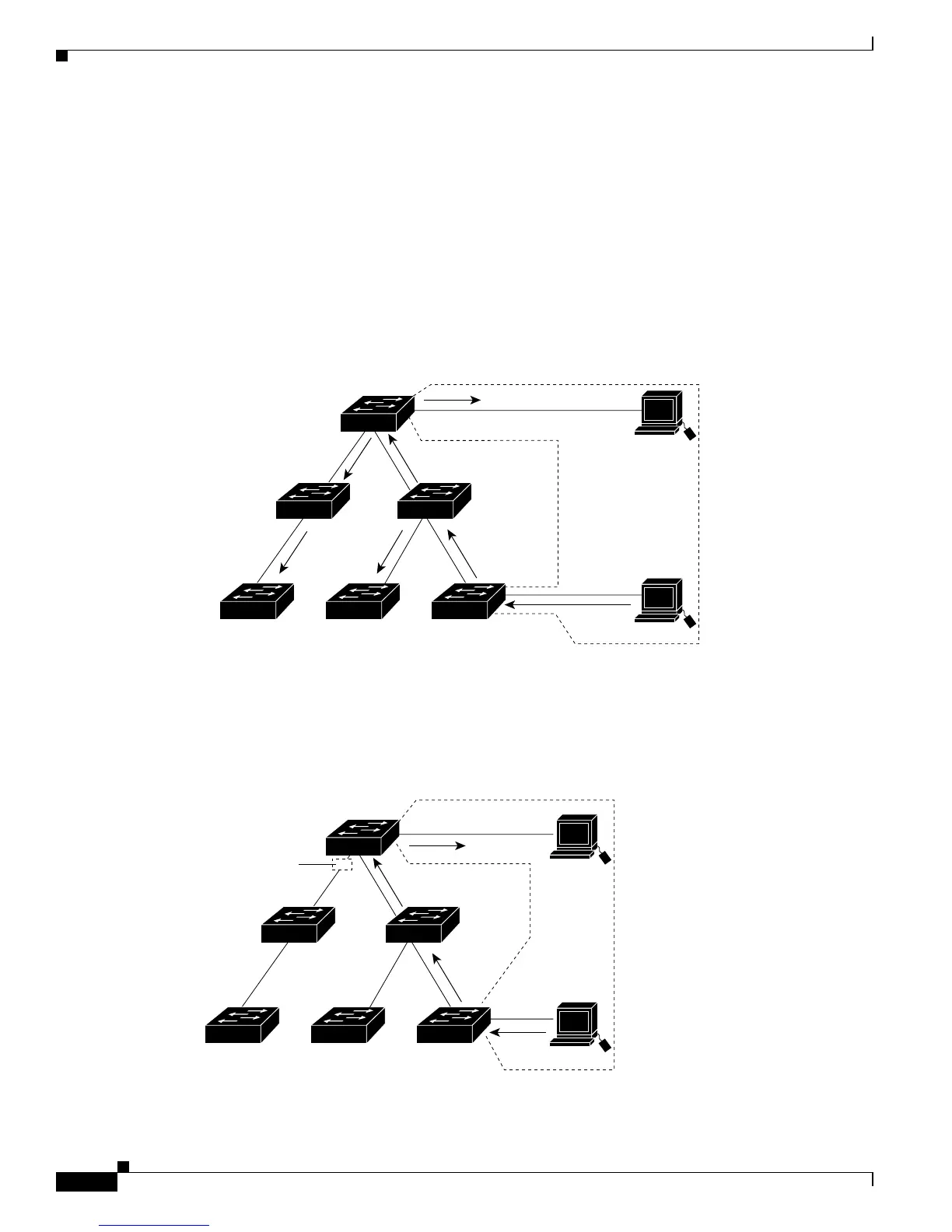
Figure 27-1 shows a switched network without VTP pruning enabled. Interface 1 on Switch 1 and
Interface 2 on Switch 4 are assigned to the Red VLAN. A broadcast is sent from the host connected to
Switch 1. Switch 1 floods the broadcast and every network device in the network receives it, even though
Switches 3, 5, and 6 have no interfaces in the Red VLAN.
You can enable pruning globally on the Catalyst 4500 series switch (see the “Enabling VTP Pruning”
section on page 27-6).
Figure 27-1 Flooding Traffic without VTP Pruning
Figure 27-2 shows the same switched network with VTP pruning enabled. The broadcast traffic from
Switch 1 is not forwarded to Switches 3, 5, and 6 because traffic for the Red VLAN has been pruned on
the links indicated (Interface 5 on Switch 2 and Interface 4 on Switch 4).
Figure 27-2 Flooding Traffic with VTP Pruning
Catalyst series
switch 4
Catalyst series
switch 5
Catalyst series
switch 3
Catalyst series
switch 6
Catalyst series
switch 1
Catalyst series
switch 2
Interface 1
Interface 2
Red
VLAN
94151
Switch 4
Switch 5
Switch 3Switch 6 Switch 1
Switch 2
Interface 1
Interface 2
Red
VLAN
31075
Interface 4
Interface 5
Flooded traffic
is pruned.