2-7
Cisco Aironet 1540 Series Outdoor Access Point Hardware Installation Guide
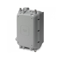
Chapter 2 Installing the Access Point
Mounting the Access Point
Note The mounting wall, attaching screws, and wall anchors must be able to support a 50 lb (22.7 kg)
static weight.
Step 3 Screw an M6 x12 mm bolt into each of the four support bolt holes on the back of the access point. Do
not screw the bolt all the way in, but leave a gap of approximately 0.13 inch (3.3 mm).
Step 4 Position the access point against mounting bracket such that the four support bolts on the back of the AP,
slot into the keyhole slots on the mounting bracket.
Step 5 Slide the access point down to seat it securely in the keyhole slots on the mounting bracket.
Note The access point should be mounted with the status LED on the base facing downwards.
Step 6 Using a 10mm wrench, tighten the four bolts that connect the access point to the bracket, to a torque of
40 lbf-in.
Step 7 Proceed with connecting the data cables, grounding the access point, powering and configuring the
access point.
 Loading...