For instructions about how to remove the AC and DC power supplies, see:
• Removing AC Power Supplies
• Removing DC Input Power Supplies
Step 2 After the power supplies are removed, remove the chassis top cover by performing the following steps:
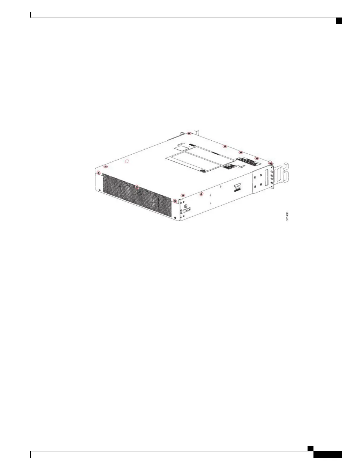
a) Remove the seven top surface screws on the chassis cover.
b) Remove the three screws from the rear of the chassis cover.
c) Remove one screw from the left side of the chassis and one screw from the right side of the chassis.
Figure 20: Cisco ASR 1002-HX RouterTop Cover Screw Locations
d) Using both hands, gently slide the cover slightly backward and lift it off of the chassis.
Step 3 Position the chassis so that you have the most comfortable access to the chassis to remove the fans.
The fans are located at the rear of the chassis.
Step 4 Unplug the four fan connectors from the motherboard.
Removing and Replacing FRUs
27
Removing and Replacing FRUs
Removing the Fans from a Cisco ASR 1002-HX Router

 Loading...


