2-50
Cisco ASR 9000 Series Aggregation Services Router Overview and Reference Guide
OL-17501-09
Chapter 2 Functional Description
Power System Functional Description
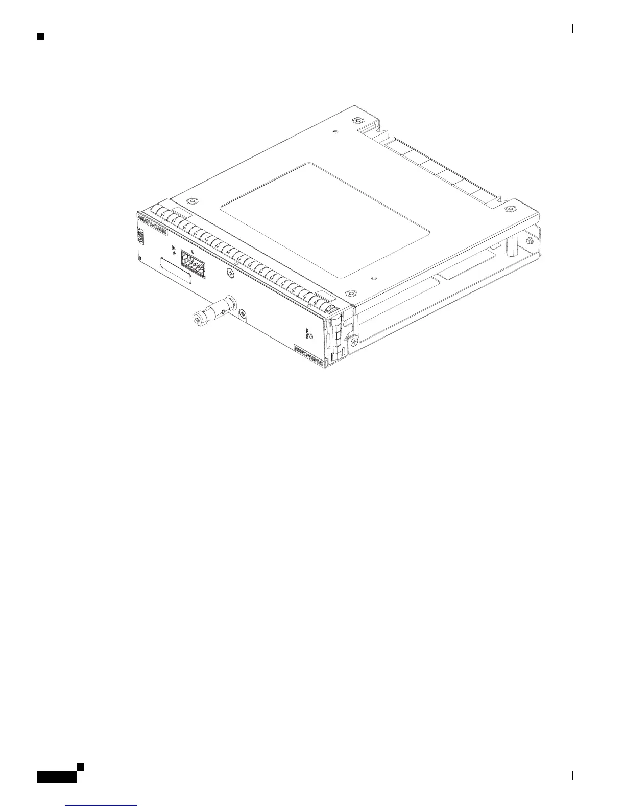
Figure 2-40 1-Port 40-Gigabit Ethernet Modular Port Adapter
Power System Functional Description
The Cisco ASR 9000 Series Routers can be powered with an AC or DC source power. The power system
is based on a distributed power architecture centered around a –54 VDC printed circuit power bus on the
system backplane.
The –54 VDC system backplane power bus can be sourced from one of two options:
• AC systems—AC/DC bulk power supply tray connected to the user’s 200 to 240 V +/- 10 percent
(180 to 264 VAC) source.
• DC systems—DC/DC bulk power supply tray connected to the user’s Central Office DC battery
source (–54 VDC nominal).
The system backplane distributes DC power from the backplane to each card and the fan trays. Each card
has on-board DC-DC converters to convert the –54 VDC from the distribution bus voltage to the voltages
required by each particular card.
The power system has single-point grounding on the –54 VDC Return, that is, the –54 VDC Return is
grounded to the chassis ground on the backplane only. In the Cisco ASR 9922 Router and Cisco ASR
9912 Router, the internal –54 VDC power distribution is isolated from the central office by the
transformers inside the power modules. It has single-point grounding on the –54 VDC Return internal
distribution bus.
All field replaceable modules of the power system are designed for Online Insertion and Removal (OIR),
so they can be installed or removed without causing interruption to system operation.
333939
 Loading...


