A-11
Cisco ASR 9000 Series Aggregation Services Router Overview and Reference Guide
OL-17501-09
Appendix A Technical Specifications
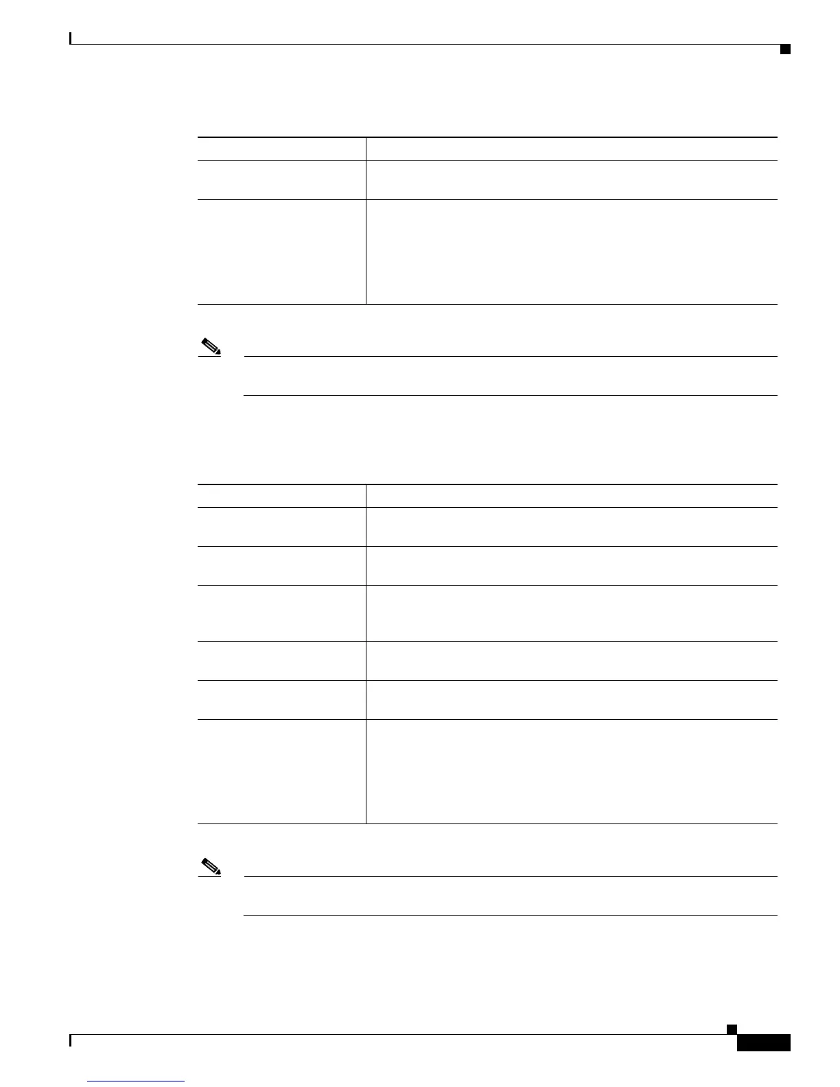
Table A-16 lists the DC electrical specifications for the Cisco ASR 9912 Router.
Source DC service
requirement
1
Sufficient to supply the rated input current. Local codes apply.
Redundancy DC power modules operate in N+1 redundancy mode. Up to sixteen
DC power modules are supported. The number of DC power modules
needed depends on the configuration of the chassis (e.g. number of line
cards, RPs, and FC cards installed). Use the Cisco Power Calculator
(Cisco.com account required) at http://tools.cisco.com/cpc/launch.jsp
to calculate how many DC power modules are needed.
1. For each DC power supply module. Some power/chassis configurations may operate at lower current ratings than those
specified in this table. Contact your Cisco technical representative for more information.
Note Both the AC-powered and DC-powered versions of the Cisco ASR 9922 Router support only
version 2 power systems.
Table A-15 Cisco ASR 9922 Router DC Electrical Specifications (continued)
Description Value
Table A-16 Cisco ASR 9912 Router DC Electrical Specifications
Description Value
Power modules per system Version 2 power system:
Up to 12 DC power modules per system, four per tray
Total DC input power per
power module
Version 2 power system:
2300 W (2100 W output module)
Rated input voltage per
power module
–48 VDC nominal in North America
–60 VDC nominal in the European Community
(Range: –40.5 to –72 VDC [–75 VDC for 5 ms])
Input current draw
1
1. For each DC power supply module. Some power/chassis configurations may operate at lower current ratings than those
specified in this table. Contact your Cisco technical representative for more information.
Note Both the AC-powered and DC-powered versions of the Cisco ASR 9912 Router support only
version 2 power systems.
49 A maximum at –48 VDC nominal
39 A maximum at –60 VDC nominal
Source DC service
requirement
1
Sufficient to supply the rated input current. Local codes apply.
Redundancy DC power modules operate in N+1 redundancy mode. Up to 12 DC
power modules are supported. The number of DC power modules
needed depends on the configuration of the chassis (e.g. number of line
cards, RPs, and FC cards installed). Use the Cisco Power Calculator
(Cisco.com account required) at http://tools.cisco.com/cpc/launch.jsp
to calculate how many DC power modules are needed.
 Loading...


