1-36
Cisco ASR 9000 Series Aggregation Services Router Overview and Reference Guide
OL-17501-09
Chapter 1 Overview and Physical Description
Cooling System
• To operate the Cisco ASR 9912 Router on AC power, three AC power trays should be installed, each
with up to four power modules which are fed by a single-phase 220-V 20-A branch circuit. Six
power modules are enough to power a fully-populated chassis. Twelve power modules are required
for N+N redundancy. Fewer power modules can be used if the chassis is populated with fewer line
cards.
• To operate the Cisco ASR 9912 Router on DC power, three DC power trays should be installed, each
with up to four power modules which are fed by separate pairs of redundant –48-V 60A branch
sources. Eleven power modules are enough to power a fully-populated chassis. Twelve power
modules are required for N+1 redundancy. Fewer power modules can be used if the chassis is
populated with fewer line cards.
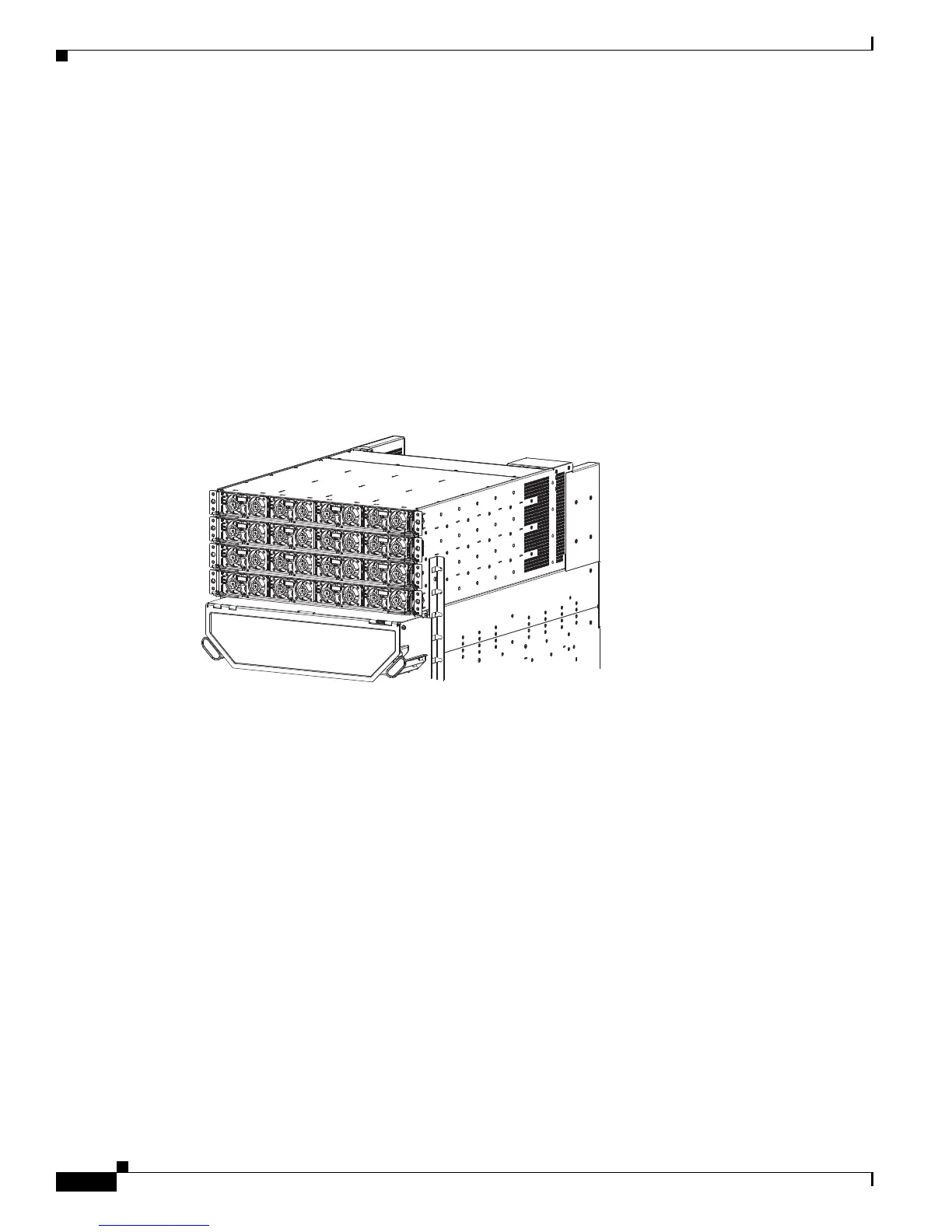
Figure 1-32 shows the front view of sixteen version 2 power modules installed in the
Cisco ASR 9922 Router.
Figure 1-32 Front System View of Power Trays —Cisco ASR 9922 Router with Version 2 Power
Tr a y s
Cooling System
The Cisco ASR 9000 Series chassis is cooled by removable fan trays. The fan trays provide full
redundancy and maintain required cooling if a single fan failure should occur.
In the Cisco ASR 9010 Router, the two fan trays are located one above the other below the card cage and
are equipped with handles for easy removal.
In the Cisco ASR 9006 Router, the two fan trays are located above the card cage, left of center, and side
by side. They are covered by a fan tray door hinged at the bottom, which must be opened before removing
the fan trays.
In the Cisco ASR 9904 Router, a single fan tray is located in the rear, right side of the card cage and is
equipped with a handle for easy insertion.
In the Cisco ASR 9922 Router, the two top fan trays are located between the top and middle cages,
whereas the two bottom fan trays are located between the middle and bottom cages. The two bottom fan
trays are inserted upside down compared to the two top fan trays. In the Cisco ASR 9912 Router, the two
fan trays are located above the line card cage. Each fan tray holds 12 axial fans and includes a controller
that reduces the speed of the fans when the chassis temperature is within limits, thereby reducing the
generation of acoustic noise. The fan controller also senses and reports individual fan failures.
 Loading...


