1-24
Cisco ASR 9000 Series Aggregation Services Router Overview and Reference Guide
OL-17501-09
Chapter 1 Overview and Physical Description
Route Switch Processor and Route Processor Cards
Route Switch Processor and Route Processor Cards
The RSP card is the main control and switch fabric element in the Cisco ASR 9010 Router, and
Cisco ASR 9006 Router, and Cisco ASR 9904 Router. To provide redundancy, there can be two RSP
cards in each router, one as the active control RSP and the other as the standby RSP. The standby RSP
takes over all control functions should the active RSP fail.
The RP card is the main control element in the Cisco ASR 9922 Router and Cisco ASR 9912 Router.
The RP card provides centralized chassis control, management, and data-plane switching. To provide
redundancy, there are two RP cards in each router, one as the active control RP and the other as the
standby RP. The standby RP takes over all control functions should the active RP fail.
On the Cisco ASR 9922 Router and Cisco ASR 9912 Router, the switch fabric has been moved to FC
cards.
RSP Front Panel and Access Ports
System alarms reside on the RSP. Alarms consist of visual indicators with three levels: Critical (red),
Major (red), and Minor (yellow). There is a console interface for remote viewing of alarms and fault
information. The RSP has the following information and alarm LEDs and connectors:
• One external Compact Flash type I/II (not on RSP-440)
• Two EIA/TIA-232 RJ232 serial RJ-45 ports—one each for Console and Auxiliary modem ports, with
Manufacturing Test connections to the backplane
• Two dual-speed 100/1000 Mbit Ethernet Management ports
• One 4 character 5x7 LED dot matrix display and discrete status LEDs
• Alarm Cut Off (ACO) and Lamp Test momentary push buttons
• Two RJ-45 Sync timing ports with Link and Fault LEDs built into the RJ-45
• Alarm Output DB9 port with three alarm outputs
PS1 M1 PM5
PS1 M2 PM6
PS1 M3 PM7
PS2 M0 PM8
PS2 M1 PM9
PS2 M2 PM10
PS2 M3 PM11
PS3 M0 PM12
PS3 M1 PM13
PS3 M2 PM14
PS3 M3 PM15
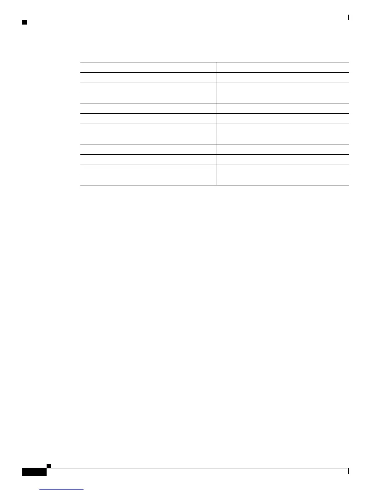
Table 1-1 Power Module Hardware and Software IDs
Hardware ID Software ID
 Loading...


