13
Step 2 Connect to the port using the RJ-45-to-DB-9 cable.
Step 3 After you establish normal router operation, you can disconnect the terminal.
Note For information about console port and auxiliary port pinouts, see the Cisco ASR 1002 Router specifications in the
Cisco ASR 1000 Series Aggregation Services Routers Hardware Installation Guide.
Connect the Ethernet Management Port
Caution To comply with Class A emissions requirements, a shielded Ethernet cable must be used.
To use the Management Ethernet interface on the router, perform the following steps:
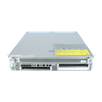
Step 1 Insert an Ethernet RJ-45 cable into the MGMT ETHERNET port (see Figure 10).
Figure 10 Cisco ASR 1002 Integrated Route Processor Ethernet Management Port Connector
Step 2 Insert the other end of the RJ-45 cable to your management device or network.
Step 3 Configure to a fixed speed through the command-line interface (CLI) commands.
Connect the Shared Port Adapter Cables
The instructions for connecting the cables for the shared port adapters installed in the Cisco ASR 1002 Router are contained in
the Cisco ASR 1000 Series Aggregation Services Routers SPA and SIP Hardware Installation Guide.
Install the Cables Using the Cable-Management Brackets
Cables coming off the front side of the Cisco ASR 1002 integrated route processor and SPAs utilize the chassis level
cable-management brackets provided on the chassis rack-mount brackets (see Figure 11).
1
MGMT port and cable
ASR 1002
stat
pwr
min
maj
cr
it
0
1
C
/
A
A
/
L
0
1
C/
A
A/
L
S
TAT
Q
E0
Q
E
1
Q
E
2
Q
E3
B
O
O
T
CA
R
RI
E
RLI
N
K
P
WR STA
TM
T
S
M
G
MT
AU
X
CO
N
S
P
A
-
4X
O
C
3
-
P
O
S
S
T
AT
U
S
0
1
2
3
C
/
A
A
/
L
C
/
A
A
/
L
C/A
A
/
L
C
/
A
A
/
L