12
Step 6 Insert the two screws through the holes in the grounding lug.
Step 7 Use the Number 2 Phillips screwdriver to carefully tighten the screws until the grounding lug is held firmly to the
chassis. Do not overtighten the screws.
Step 8 Connect the opposite ends of the grounding wire to the appropriate grounding point at your site to ensure an adequate
chassis ground.
This completes the procedure for attaching a chassis ground connection. Go to the procedure described in the “Connect the
Router to the Network” section on page 12 for information about connecting the router to the network. .
4 Connect the Router to the Network
This section provides information about cables and ports and attaching the router to the network.
• Console Port Cable and Auxiliary Port Cable Connections, page 12
• Connect the Ethernet Management Port, page 13
• Connect the Shared Port Adapter Cables, page 13
• Install the Cables Using the Cable-Management Brackets, page 13
Console Port Cable and Auxiliary Port Cable Connections
This section describes how to attach a cable to the console port or auxiliary port on the Cisco ASR 1002 Router. The Cisco
ASR 1002 Router uses RJ-45 ports for both the auxiliary port and the console port to attach a modem or console terminal.
The console DCE mode port connects a console terminal, and a DTE mode auxiliary port connects a modem or other DCE
devices to your router.
Caution Both the console port and the auxiliary port are asynchronous serial ports; devices connected to these ports must
be capable of asynchronous transmission. (Asynchronous is the most common type of serial device, for example,
most modems are asynchronous devices.) To meet Class A emission requirements on the Cisco ASR 1002 Router,
shielded cables must be used for the console port and auxiliary port connections.
Perform the following steps to connect the console port cable and auxiliary port cable.
Step 1 Before connecting a terminal to the console port, configure the terminal to match the router console port as follows:
9600 baud, 8 data bits, no parity, 1 stop bit. See Figure 9 for the console port and auxiliary port connector location.
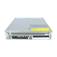
Figure 9 Cisco ASR 1002 Integrated Route Processor Console port and Auxiliary Port Connectors
1
CON—console port
2
AUX—auxiliary port
ASR 1002
stat
pw
r
min
maj
cr
it
0
1
C
/
A
A
/
L
0
1
C/
A
A/
L
S
TAT
Q
E0
Q
E
1
QE
2
Q
E3
B
O
O
T
CA
R
RI
E
RLI
N
K
P
WR STA
TM
T
S
M
G
MT
AU
X
CO
N
S
P
A
-
4X
O
C
3
-
P
O
S
S
T
AT
U
S
0
1
2
3
C
/
A
A
/
L
C
/
A
A
/
L
C/A
A
/
L
C
/
A
A
/
L