D14637.10 Profile C20 and Quick Set C20 Administrator Guide TC6.1, APRIL 2013. www.cisco.com — Copyright © 2010-2013 Cisco Systems, Inc. All rights reserved.
116
Cisco TelePresence System Quick Set C20 and Profiles using C20 Administrator Guide
Pin: 19 17 3 1
Pin: 18 16 4 2
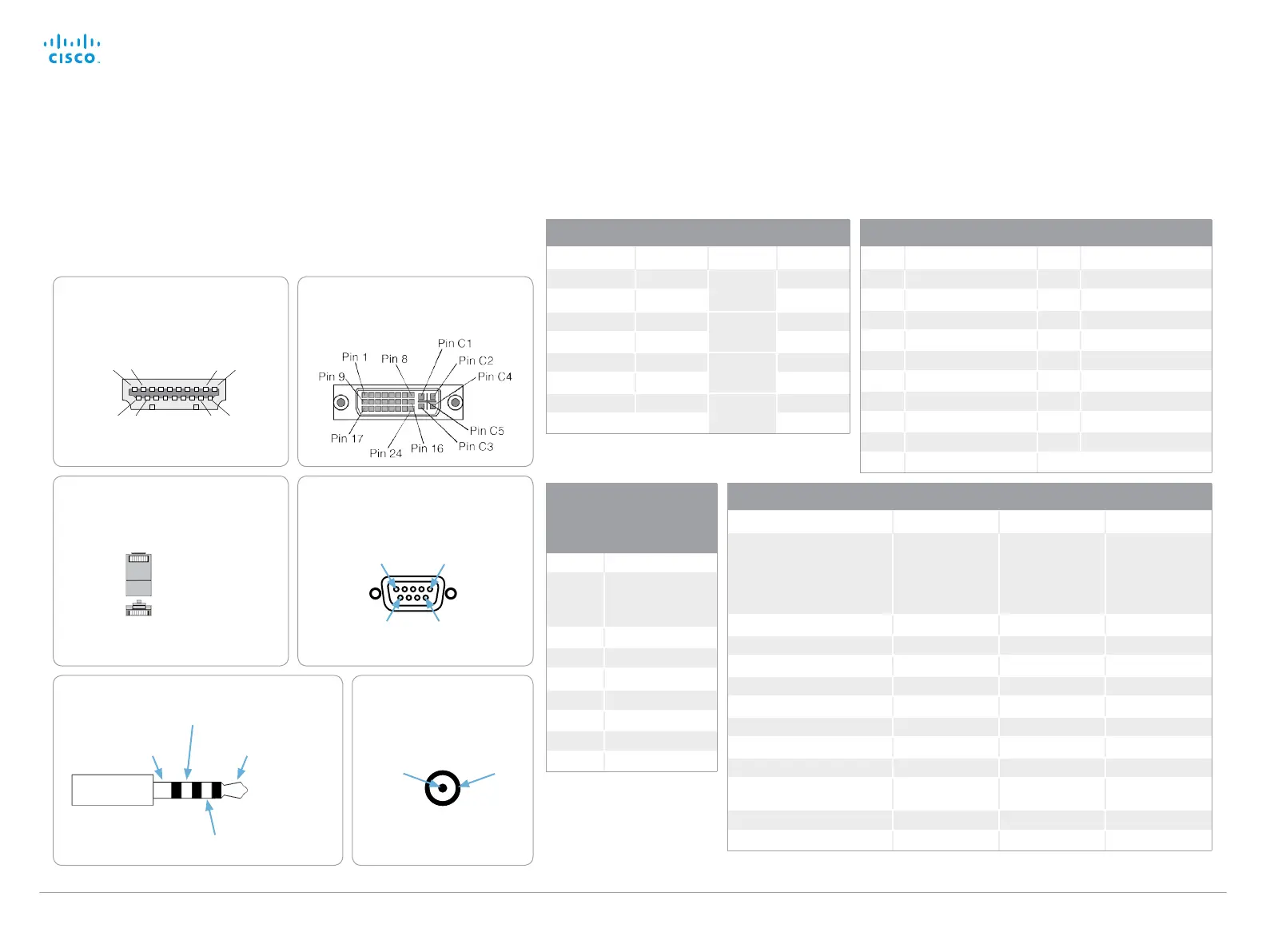
HDMI pin-out
External view of socket
DVI-I pin-out
External view of socket
RCA pin-out
External view of socket
GND
Signal
RJ-45 Connector pin-out
1 ---------- 1
2 ---------- 2
3 ---------- 3
6 ---------- 6
Wiring diagram
standard cable
TOP
FRONT
1 8
1 8
RS232 9 pin D-SUB pin-out
External view of socket
1 5
6 9
Pin-out schemes
This page gives an overview of the pin-out schemes for C20.
HDMI Pin-out
Pin Assignment Pin Assignment
1 T.M.D.S. Data 2+ 11 T.M.D.S. Clock Shield
2 T.M.D.S. Data 2 Shield 12 T.M.D.S. Clock–
3 T.M.D.S. Data 2 – 13 CEC
4 T.M.D.S. Data 1 14 Reserved (N.C. on device)
5 T.M.D.S. Data 1 Shield 15 SCL
6 T.M.D.S. Data 1 – 16 SDA
7 T.M.D.S. Data 0 17 DDC/CEC Ground
8 T.M.D.S. Data 0 Shield 18 +5 V Power (max 50 mA)
9 T.M.D.S. Data 0– 19 Hot Plug Detect
10 T.M.D.S. Clock+
Pin-out—Camera cable
Signal name RJ-45 pin D-SUB pin
+12 V DC 1 Twisted pair 4
GND 2 5
RX 3 Twisted pair 2
TX 6 3
NC 4 Twisted pair 1
NC 5 6
GND 7 Twisted pair 5
+12 V DC 8 4
Pin-out—VISCA™
camera control
RJ11, 8 pins shielded
modular jack
Pin Signal name
8 +12 V (presence
2.8 mA current source
when connected in
daisy chain)
7 GND
6 TXD (out)
5 NC (no connect)
4 NC (no connect)
3 RXD (in)
2 GND
1 +12 V
Codec C20 audio connectors
Jack Mic input RCA line input RCA line output
Connector pin out Tip = Hot
Ring 1 = Cold
Ring 2 = Mic. control
Shield = GND
Pin = Signal
Shield = GND
Pin = Signal
Shield = GND
Signal type Balanced Unbalanced Unbalanced
Connector (codec) Mini Jack 3.5 mm Female RCA/phono Female RCA/phono
Input impedance 1.5 kOhm/leg 18k Ohm
Output impedance 100 Ohm
Maximum input level -18.3 dBu +/-2 dB 9.0 dBu +/-2 dB
Maximum output level 8.2 dBu +/-2 dB
Phantom power 12 V +/-1 V
Phantom power resistor pin ”tip” 1.7 k Oh m
Phantom power resistor pin
”ring 1”
1.7 k Oh m
Frequency response 20 Hz-20 kHz +/-1 dB 20 Hz-20 kHz +/-1 dB 20 Hz-20 kHz +/-1 dB
Signal to Noise Ratio -85 dB -95 dB -95 dB
Microphone, 3.5 mm Mini-Jack, 4 pole
Microphone control
Ground Audio – Hot
Audio – Cold

 Loading...