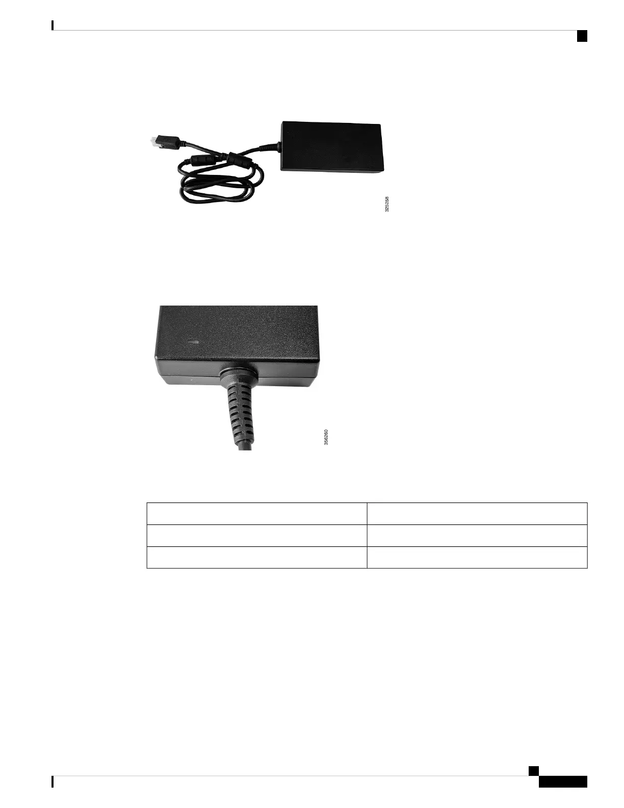
Figure 16: DC Power Cord
Verifying Connections
To verify if the power supply adapter is connected to the power outlet, first turn on the power, then check the
LED status.
Figure 17: LED Location
The following table describes the LED status of the power supply adapter.
Table 8: Power Supply Adapter LED and Description
DescriptionPower Supply Adapter LED
No input power.Off (LED is off)
Input power present.Green
Installation Guidelines
This section includes the basic installation guidelines for installing a power supply. Read this section before
you start the installation procedure. Translations of the warning statements appear in the RCSI guide on
Cisco.com.
Observe these guidelines when installing a power supply:
• A power supply that is only partially connected to the controller can disrupt the system operation.
Cisco Catalyst 9800-L Wireless Controller Hardware Installation Guide
29
Installing the Power Supply
Installation Guidelines

 Loading...


