• Top Cover
• Mounting Plate
• Bottom Cover
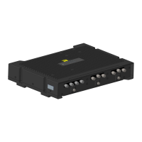
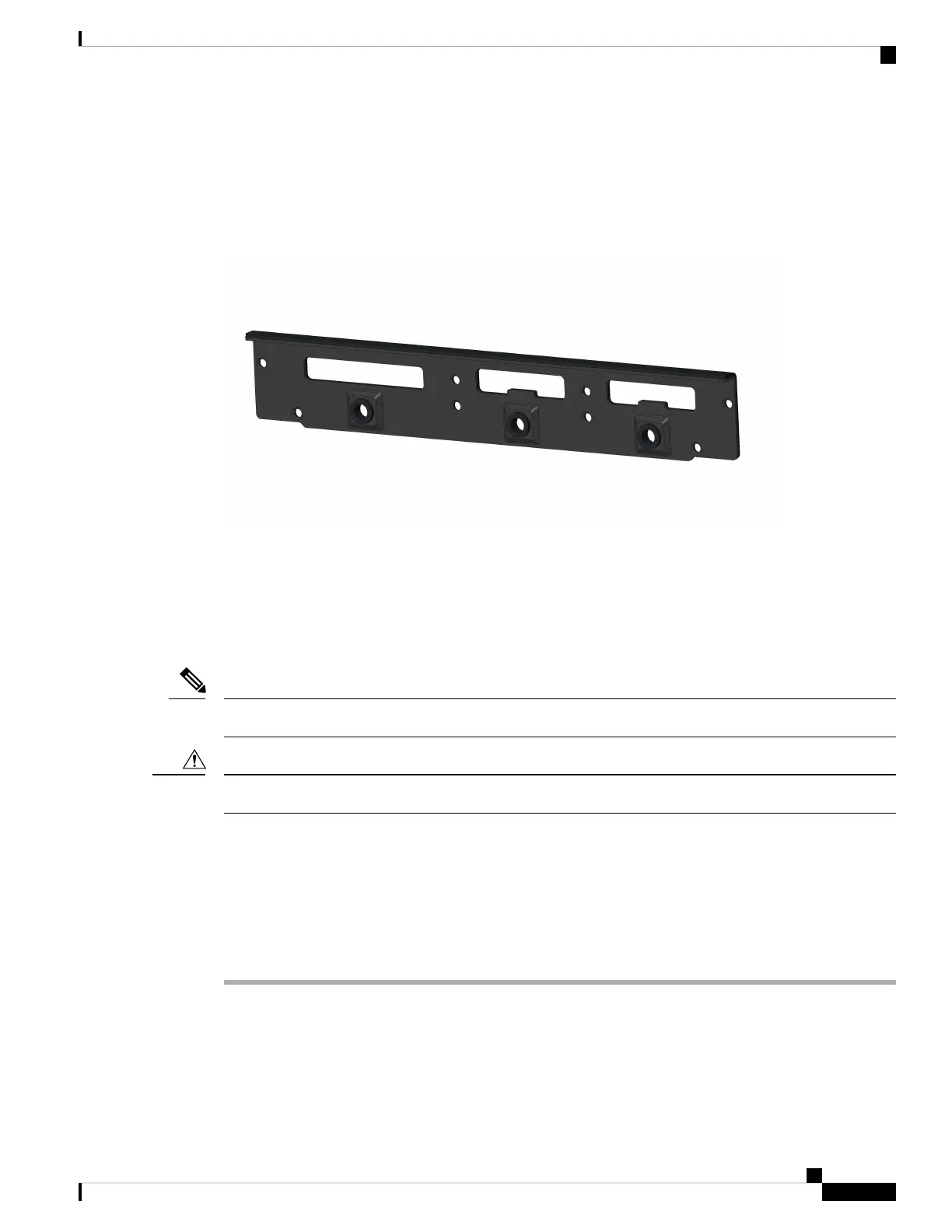
Figure 29: Back Cover Parts
The IP54 Back Cover ships as one piece with 8 screws.
Installing the IP54 Kit
This section provides an overview of the IP54 kit installation.
Ensure that you are using proper static discharge techniques such as a wrist strap and static mat.
Note
Ensure the device is powered down before performing any removal or installation of a module.
Caution
Installing the Front Cover
The Front Cover of the IP54 kit is installed around the IR1800 from the four parts previously listed and the
screws provided.
Procedure
Step 1 Make sure all cables are removed and that the desired FRUs or blanks are installed before assembling the
front IP54 cover.
Step 2 Attach the mounting plate to the front of the chassis using four of the provided screws. See the following
graphic:
Cisco Catalyst IR1800 Rugged Series Router Hardware Installation Guide
71
Installing the IP54 Kit
Installing the IP54 Kit
 Loading...