Step 3 Tighten the screws to a torque of 5 to 6 in-lbs.
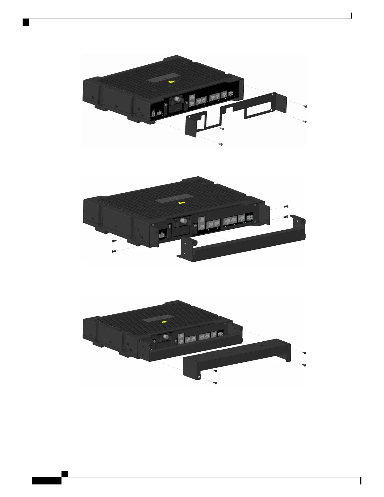
Step 4 Attach the bottom cover to the mounting plate using four of the provided screws. See the following graphic:
Step 5 Plug in the power and all other desired cables after the bottom cover is attached. Drape all cables over the
foam seat.
Step 6 Attach the top cover to the bottom cover using four of the provided screws. See the following graphic:
All cables should be wedged between the top and bottom foam pieces.
Note
Step 7 Attach the top cover plate to the top cover using four more of the provided screws. See the following graphic:
Cisco Catalyst IR1800 Rugged Series Router Hardware Installation Guide
72
Installing the IP54 Kit
Installing the Front Cover
 Loading...