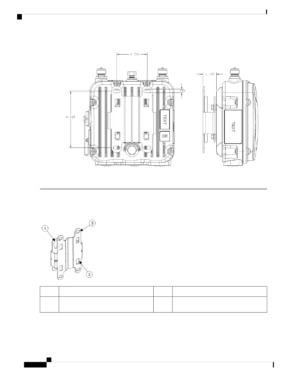
Figure 13: Mounting Bracket Dimensions
To mount the access point on a vertical wall, follow these instructions:
Step 1 Use the mounting bracket as a template to mark four screw hole locations on the mounting surface. See the following
figure for the mounting bracket screw hole locations. Use the mounting slotted holes to attach the unit to the wall.
Figure 14: Mounting Bracket Screw Hole Locations
Mounting Slots (used with the band clamps)2Quick Mount Keyhole Slots (for AP use)1
Bracket Mount Holes (use bolts up to 1/4" or 6
mm in diameter)
3
Step 2 Use four customer-supplied screws and optional screw-anchors to attach the mounting plate to the mounting surface.
Step 3 Screw an M6 x12 mm bolt into each of the four support bolt holes on the back of the access point. Do not screw the bolt
all the way in; leave approximately a 0.13 inch (3.3 mm) space.
Cisco Catalyst IW9165D Heavy Duty Access Point Hardware Installation Guide
20
Installation Overview
Wall Mounting the Access Point with the Fixed Mounting Kit