2-3
Cisco CRS-1 Carrier Routing System SIP and SPA Hardware Installation Guide
OL-17439-01
Chapter 2 Overview: Cisco CRS-1 SPA Interface Processor
Identifying Slots and Subslots for SIPs and SPAs
Identifying Slots and Subslots for SIPs and SPAs
The following sections describe SIP, SPA, and interface numbering:
• SIP Slot Locations on the Cisco CRS-1 Router, page 2-3
• SPA Slot Numbering on the Cisco CRS-1 SIP-800, page 2-4
• SPA Interface Addresses on SIPs, page 2-6
SIP Slot Locations on the Cisco CRS-1 Router
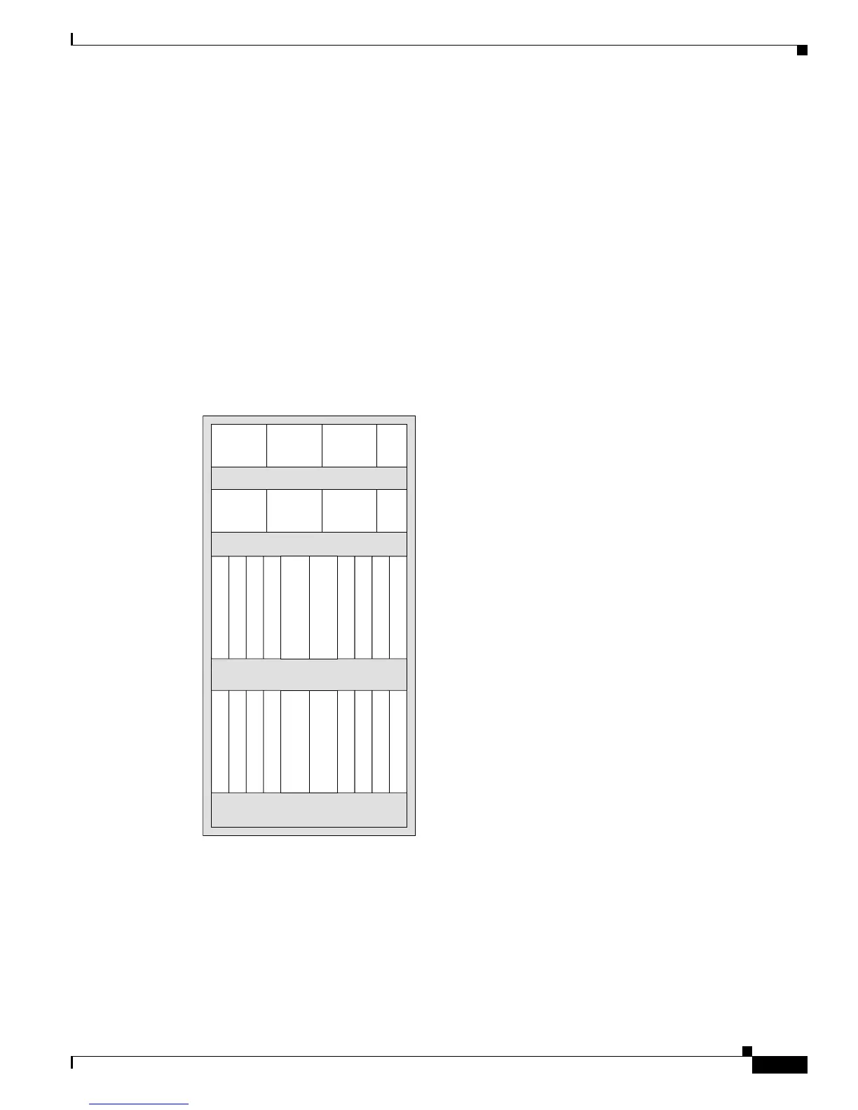
A SIP can be installed in PLIM slots 0 through 15 on the Cisco CRS-1 router 16-slot line card chassis
and PLIM slots 0 through 7 on the Cisco CRS-1 router 8-slot line card chassis. Figure 2-2 and Figure 2-3
show the slot numbering on the front (PLIM side) of the line card chassis.
Figure 2-2 16-Slot Line Card Chassis Slot Numbers—Front (PLIM) View
101931
0 1 2 3 4 5 6 7FC0 FC1
8 9 10 11 12 13 14 15RP0 RP1
A0
B0
A1
B1
PS0 (Power shelf)
PS1 (Power shelf)
Upper PLIM card cage
Lower PLIM card cage
A2
B2
AM0
AM1
 Loading...


