3-43
Cisco CRS-1 Carrier Routing System SIP and SPA Hardware Installation Guide
OL-17439-01
Chapter 3 Overview: Cisco CRS-1 Shared Port Adapters
2-Port and 4-Port Clear Channel T3/E3 SPA Overview
2-Port and 4-Port Clear Channel T3/E3 SPA Overview
The following sections describe the 2-Port and 4-Port Channelized T3 SPA:
• 2-Port and 4-Port Channelized T3 SPA LEDs, page 3-43
• 2-Port and 4-Port Channelized T3 SPA Interface Specifications, page 3-44
• 2-Port and 4-Port Channelized T3 SPA Cables and Connectors, page 3-44
2-Port and 4-Port Channelized T3 SPA LEDs
The 2-Port and 4-Port Channelized T3 SPA has three types of LEDs. There are two LEDs for each port
on the SPA, and one STATUS LED. Figure 3-26 s
hows an example of these LEDs on a 4-Port
Channelized T3 SPA.
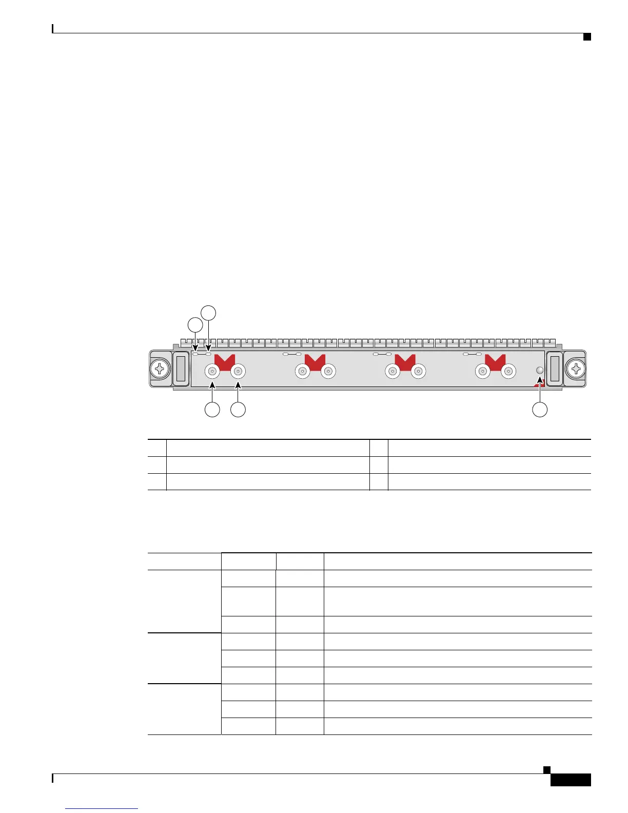
Figure 3-26 4-Port Channelized T3 SPA Faceplate
The 2-Port and 4-Port Channelized T3 SPA LEDs are described in Table 3-30.
1 C/A (Carrier/Alarm) LED 4 RX (Receive) connector
2 A/L (Active Loopback) LED 5 STATUS LED
3 TX (Transmit) connector
C/A
TX
RX
1
STATUS
SPA-4XCT3/DS0
0
A/L
C/A
TX
RX
A/L
C/A
TX
RX
2
A/L
C/A
TX
RX
3
A/L
1
2
3 4 5
116854
Ta b l e 3-30 2-Port and 4-Port Channelized T3 SPA LEDs
LED Label Color State Meaning
C/A Off Off Port is not enabled by software.
Green On Port is enabled by software, and
there is a valid E3 or T3
signal without any alarms.
Amber On Port is enabled by software, and
there is at least one alarm.
A/L Off Off Port is not enabled by software.
Green On Port is enabled by software, loopback is off.
Amber On Port is enabled by softw
are, loopback is on.
STATUS Off Off SPA power is off.
Green On SPA is ready and operational.
Amber On SPA power is on and good, and SPA is being configured.
 Loading...


