EasyManuals Logo

Cisco Firepower 1010 Hardware Installation Guide

Cisco Firepower 1010
50 pages
To Next Page IconTo Next Page
To Previous Page IconTo Previous Page
Page #33 background imageLoading...
Page #33 background image
Three Phillips M3 x 6-mm screws (part number 48-0460-01)
Two Phillips #6 x 1¼-inch screws (part number 48-2289-01)
One #8 wall anchor kit with screws (part number 51-4718-01)
Follow these steps to mount your chassis on a wall.
Step 1 Choose an orientation (left-, right-, or rear panel-side up) and a location on the wall for the chassis.
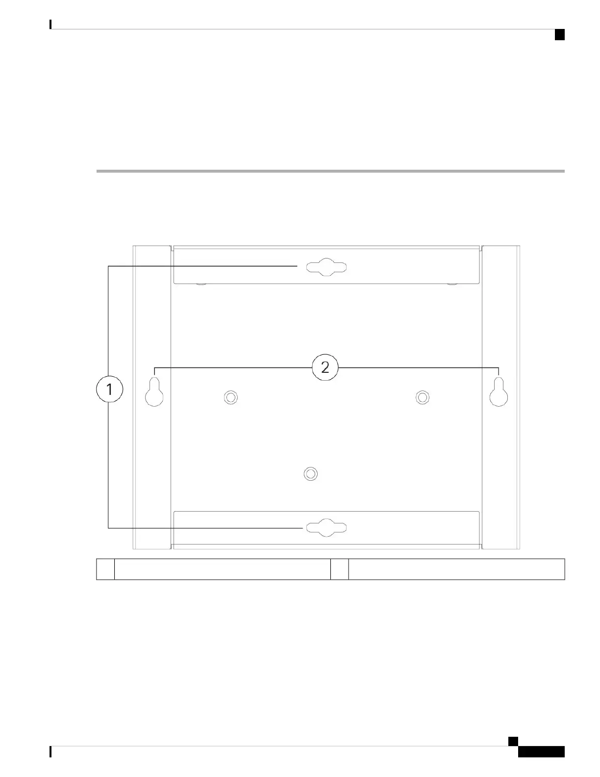
Step 2 Use a pencil, ruler, and level to mark locations for the two mounting screws (#6 x inch). You can use the wall-mount
bracket itself to mark either the top holes or the side holes.
Figure 26: Wall-Mount Bracket
Vertical mounting2Horizontal mounting1
Step 3 Attach the wall-mount bracket to the chassis using the three Phillips M3 x 6-mm screws.
Cisco Firepower 1010 Hardware Installation Guide
29
Mount the Chassis
Wall-Mount the Chassis

Other manuals for Cisco Firepower 1010

Questions and Answers:

Question and Answer IconNeed help?

Do you have a question about the Cisco Firepower 1010 and is the answer not in the manual?

Cisco Firepower 1010 Specifications

General IconGeneral
VPN Throughput500 Mbps
Concurrent Sessions100, 000
Maximum Concurrent Sessions200, 000
Ports8 x 1 GE
Humidity10% to 90% non-condensing
Form FactorDesktop
Flash Memory8 GB
Interfaces8 x RJ-45
Power SupplyInternal
Dimensions (H x W x D)4.44 x 21.59 x 17.27 cm
Operating Temperature32°F to 104°F (0°C to 40°C)
Storage Temperature-20 to 70°C
Memory4 GB

Related product manuals