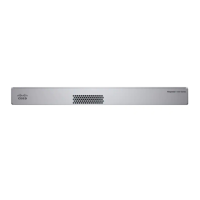
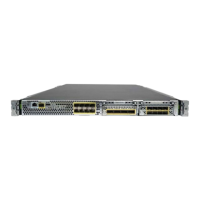
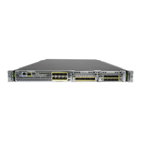
Do not mount the chassis with the rear panel facing downward. This orientation is not supported.
Caution
Step 9 To uninstall the chassis from the wall mount, slide the wall-mounted chassis from the wall, and remove the three screws
from the bottom of the chassis.
What to do next
If you are installing a FIPS cover on the chassis, follow the steps in Install the FIPS Opacity Shield , on page
41.
Install the cables according to your default software configuration as described in the Cisco Firepower 1010
Getting Started Guide.
Rack-Mount the Chassis
The rack-mount kit (800-107605-01) contains the following items:
There are two sets of four screws that you can use to secure the chassis to your rack. Chose the screws that
fit your rack.
Note
• Rack shelf (part number 700-122662-01)
• Two sliding rack trays (part number 800-107648-01)
• Two cable guides (part number 700-122664-01)
• Twelve Phillips M3 x 7-mm screws (part number 48-1921-01); use these screws to install the cable guides
and to secure the rack shelf onto the chassis.
• Four Phillips 12-24 x 0.75-inch screws (part number 48-0440-01); depending on your rack type, use
these screws to secure the sliding-rack tray to your rack.
• Four Phillips 10-32 x 0.75-inch screws (part number 48-0441-01); depending on your rack type, use
these screws to secure the sliding-rack tray to your rack.
Step 1 Install the cable guides on the rack shelf:
Cisco Firepower 1010 Hardware Installation Guide
31
Mount the Chassis
Rack-Mount the Chassis
 Loading...


