EasyManuals Logo

Cisco Firepower 1010 Hardware Installation Guide

Cisco Firepower 1010
50 pages
To Next Page IconTo Next Page
To Previous Page IconTo Previous Page
Page #37 background imageLoading...
Page #37 background image
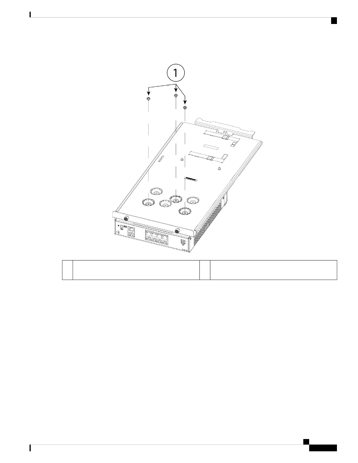
Figure 29: Install the Sliding Rack Tray on the Chassis
Three of the twelve M3 x 7-mm screws (part number
48-1921-01)
1
Step 4 Adjust the position of the chassis and the sliding rack tray until the three mounting holes in the dimples in the bottom
of the sliding rack tray are aligned with the mounting holes in the bottom of the chassis.
Step 5 Tighten the three M3 x 7-mm screws to lock the chassis into place on the sliding rack tray (see the figure above).
Step 6 Carefully turn the sliding rack tray right-side up.
Step 7 Install the power supply in the sliding rack tray behind the chassis.
Cisco Firepower 1010 Hardware Installation Guide
33
Mount the Chassis
Rack-Mount the Chassis

Other manuals for Cisco Firepower 1010

Questions and Answers:

Question and Answer IconNeed help?

Do you have a question about the Cisco Firepower 1010 and is the answer not in the manual?

Cisco Firepower 1010 Specifications

General IconGeneral
VPN Throughput500 Mbps
Concurrent Sessions100, 000
Maximum Concurrent Sessions200, 000
Ports8 x 1 GE
Humidity10% to 90% non-condensing
Form FactorDesktop
Flash Memory8 GB
Interfaces8 x RJ-45
Power SupplyInternal
Dimensions (H x W x D)4.44 x 21.59 x 17.27 cm
Operating Temperature32°F to 104°F (0°C to 40°C)
Storage Temperature-20 to 70°C
Memory4 GB

Related product manuals