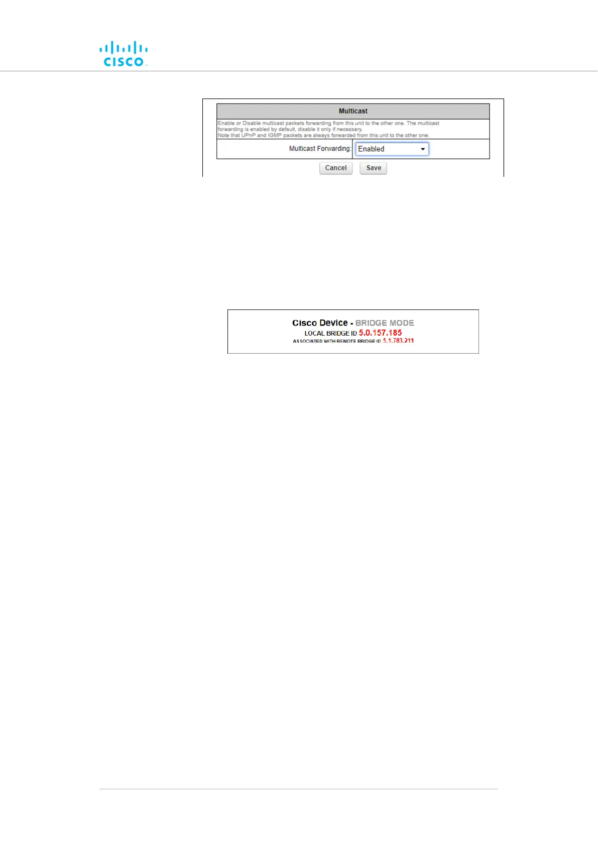
Figure 41. Multicast dialog (Bridge mode)
• The
unit ID number of the local unit is shown as the
LOCAL BRIDGE ID (Figure 42 (page 103)).
• The unit ID number of the Bridge unit to which the local unit
is linked is shown to the right of 'ASSOCIATED WITH
REMOTE BRIDGE ID'.
Figure 42. Configurator interface (Unit ID information)
3. Choose
the Enabled or Disabled option from the Multicast
Forwarding: drop-down menu.
4. Save the multicast settings by clicking the Save button.
Alternatively, clear the settings by clicking the Reset button.
Configuring Multicast within a Layer-3 network
Within a typical Layer-3 network, consider a scenario in which Multicast
traffic must be routed in both directions between Fluidity-enabled, vehicle-
mounted radio transceivers, and the global gateway unit that governs data
traffic through the core network.
In the case above, since different multicast groups must be used for
upstream and downstream traffic, consider that group designator
224.5.5.5 is being used to route traffic from the vehicle radios to the global
gateway, and that group designator 224.5.5.6 is being used to route traffic
from the global gateway to the vehicle radios.
Apply the needed multicast rules by doing the steps that follow:
1. Identify all Mesh End units belonging to each subnet cluster in the
Layer-3 network.
2. Enable upstream (vehicle to infrastructure) Multicast traffic by
adding multicast route 224.5.5.5 / 5.a.b.c to the Mesh End unit in
each subnet cluster, where 5.a.b.c is the actual Mesh ID number
of the global gateway unit.
Device configuration using the configurator interface
© 2021 Cisco and/or its affiliates. All rights reserved. Page 103 of 175