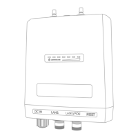
5.1.3. Cisco FM1200 Volo Status and link LEDs
Unit and link quality status
The
front panel of the Cisco FM1200 Volo (as seen below) contains seven
LEDs. The panel is used to check the unit status and wireless link quality
status.
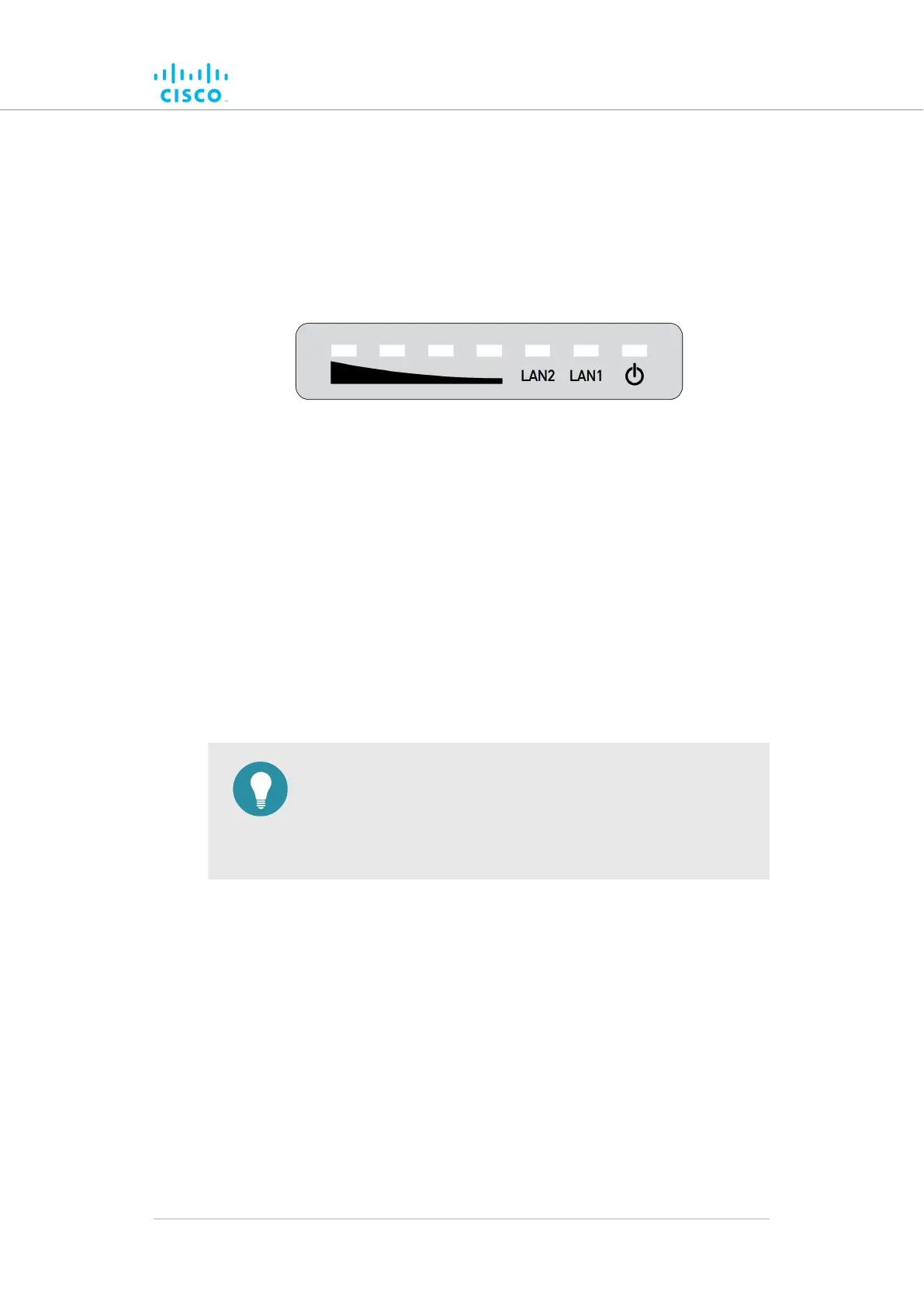
Figure 7. Status and link/boot LEDs
During
normal operation, the seven LEDs indicate the following
conditions:
• Power: The Cisco FM1200 Volo is receiving power.
• LAN1: Network activity on Ethernet port 1.
• LAN2: Network activity on Ethernet port 2.
• SIGNAL STRENGTH (red): Signal strength very poor.
• SIGNAL STRENGTH (yellow): Signal strength inadequate.
• SIGNAL STRENGTH (green): Signal strength acceptable.
• SIGNAL STRENGTH (green): Signal strength excellent.
TIP
During
normal operation, the readings from the four SIGNAL
STRENGTH LEDs can be used to do radio antenna alignment
(see “Antenna-alignment tools and physical statistics” (page
68) for more information).
Boot sequence
During the unit's boot sequence, the four SIGNAL STRENGTH LEDs light
up in sequence. During the boot sequence, the LEDs indicate the
following conditions:
1. Red: Core system boot in progress.
2. Yellow: Wireless system boot in progress.
3. First green: Routing engine boot in progress.
4. Second green: Unit configuration boot in progress.
If the boot sequence above stops at any LED, an error has been detected
during that stage of the boot sequence.
Hardware installation
© 2021 Cisco and/or its affiliates. All rights reserved. Page 30 of 175