1-5
Cisco IR829 Integrated Services Router Hardware Installation Guide
Chapter 1 Product Overview
General Description
Figure 1-7 RSSI LED
GPS GPS Status Off — GPS not configured
On — GPS configured
Slow Flash — GPS Acquiring in Standalone GPS
Fast Flash — GPS Acquiring in Assisted GPS
Note Slow Flash is defined as the LED will be on for
0.25 seconds and off for 0.75 seconds.
Fast Flash s defined as the LED will be on for
0.25 seconds and off for 0.25 seconds.
MOD
Ethernet LAN
Switch Ports
GE1-GE4]
Single LED per
Port
Link Status/POE Status Off — No link
Green Steady on — Link is up
Green Blink — Transmitting and Receiving data
Yellow — POE Fault, implies no link
WLAN 2.4GHz
5GHz
Off — Radio is down (no SSID configured)
Flashing Green — Bootloader, IOS Ethernet
Initialization, IOS Start Up after system initialization.
Green to Red to Yellow — Discovery/Join process.
Rapid Flashing Green — Joined to a controller
Steady Green — One wireless client is associated.
CELLULAR0/
CELLULAR1
ACT
Off — Module not powered on
On — Module is powered on and connected but not
transmitting or receiving
Slow Blink — Module is powered on and searching for
connection
Fast Blink — Module is transmitting or receiving.
CELLULAR0/
CELLULAR1
RSSI
The RSSI LEDs are a 3 LED bar graph to indicate signal
strength. Their functionality is described in the RSSI LED
figure below.
SIM0/SIM1 Sim cards
Off — No USIM
Green — USIM installed and active
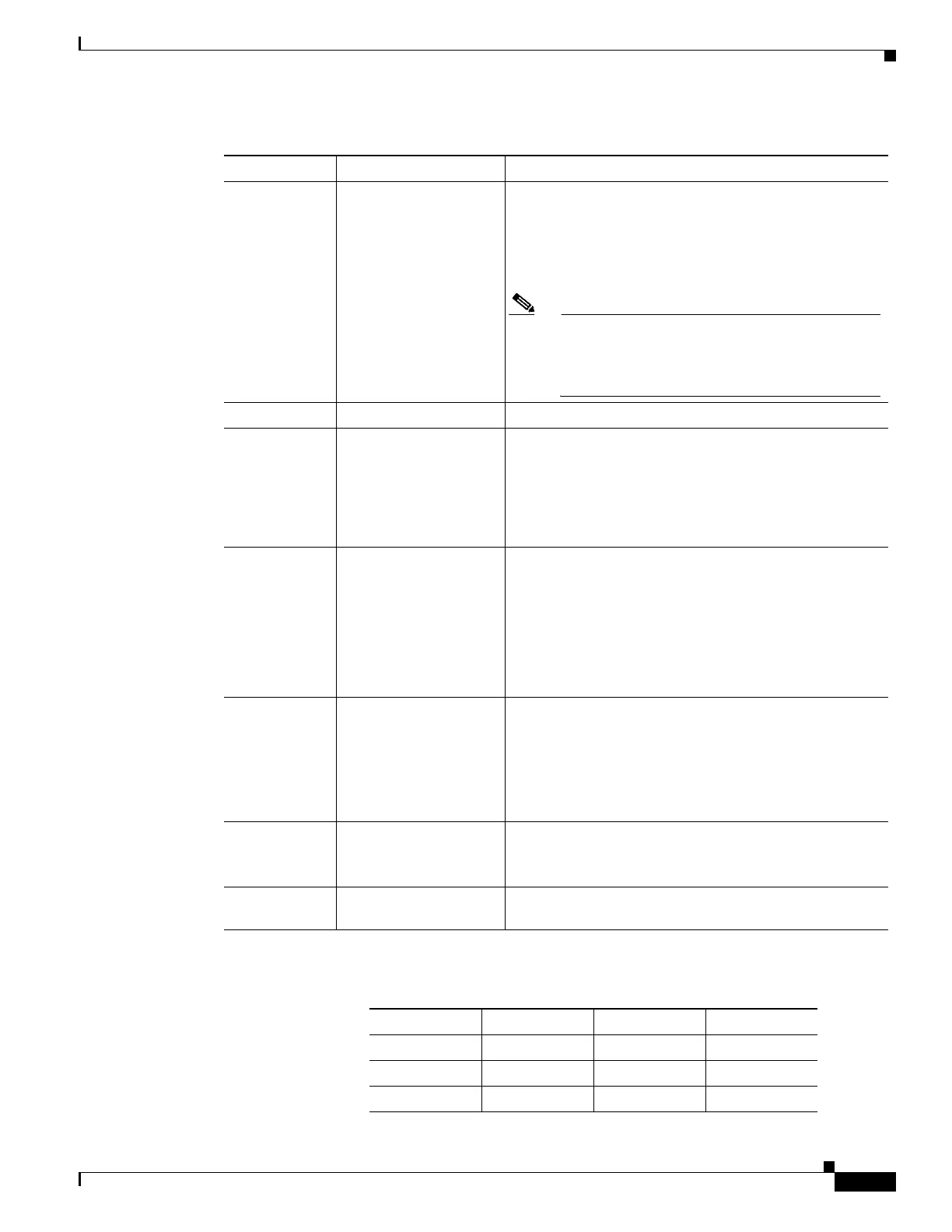
Table 1-1 LED Descriptions (continued)
LED Activity Description
RSSI RSSI (2) RSSI (1) RSSI (0)
Green Green Green/Yellow
<110dBm Off Off Off
-110 — 90dBm Off Off On - Yellow