3-4
Cisco IR829 Integrated Services Router Hardware Installation Guide
Chapter 3 Connecting the Router
Connecting to DC Power
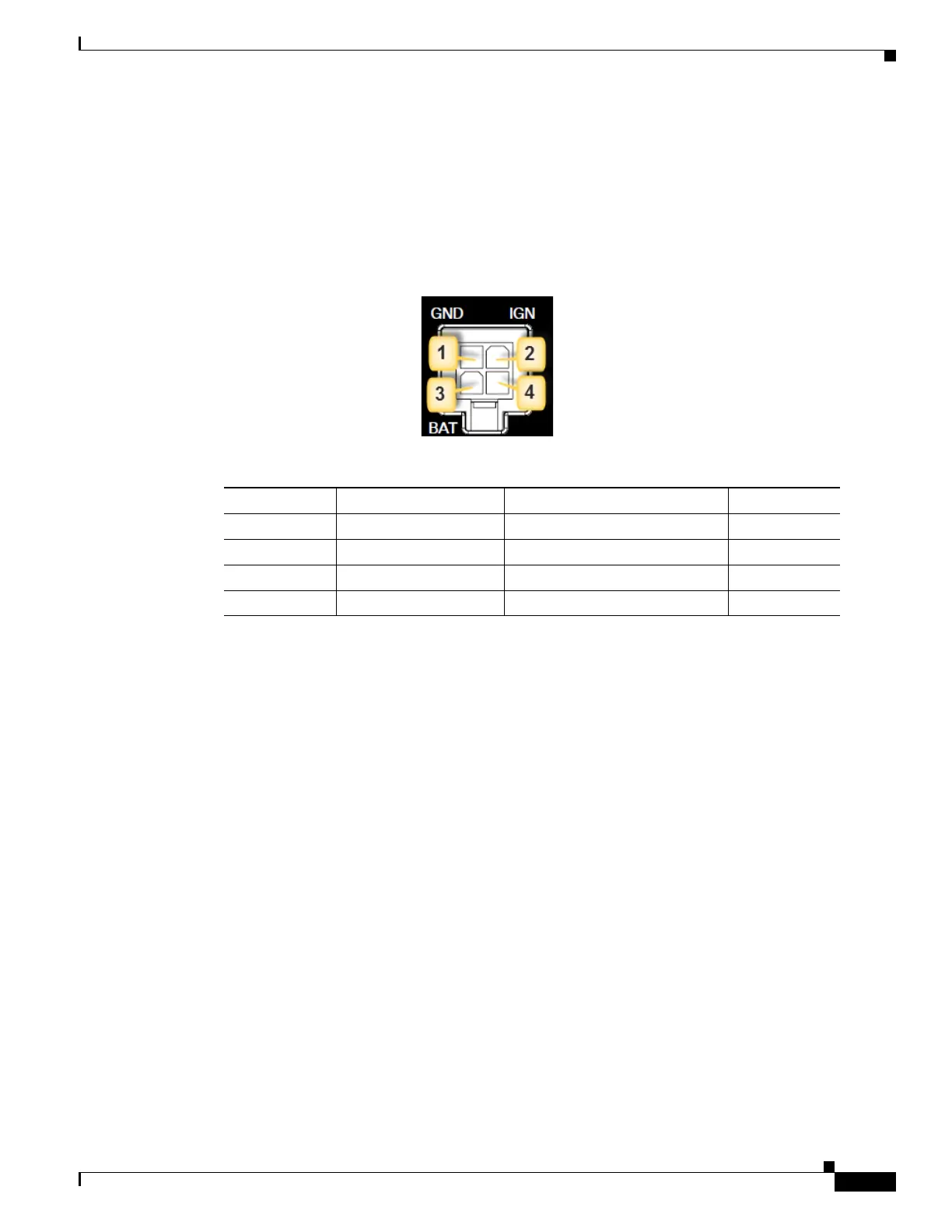
Plugs and Pin-Outs
The IR829 ships with a DC power accessory kit that contains a 4-pin locking connector and pins to use
for the power connections. Four contacts are supplied, but only three are used. One is a spare.
The power entry receptacle is on the IR829. The pin-outs are shown in Figure 3.
Figure 3 Power Connector Pin-outs
Figure 4 Power connector Descriptions
Constructing a Power cable
Special care should be taken when making the connections for DC power. It is easy to make a mistake
when crimping connections, and there is a very good tutorial available at Molex:
http://www.molex.com/tnotes/crimp.html
The specifications for the wiring are as follows:
• 16 AWG (1.02-to-1.29mm)
• UL1015 Rated
• Wires will be wound at 1 twist per inch
The example in Figure 3-5 shows a cable constructed with a ferrite for a different certification. You can
build your cable without the ferrite eliminating items 2 and 3 in the diagram.
Pin Number Name Description Color
1 DC In - DC Power Return (GND-) Black
2 Ignition Ignition Input (IGN) Blue
3 DC In + DC Power In (BAT+) Red
4N/A N/A N/A