1-9
Cisco IR829 Integrated Services Router Hardware Installation Guide
Chapter 1 Product Overview
Antennas
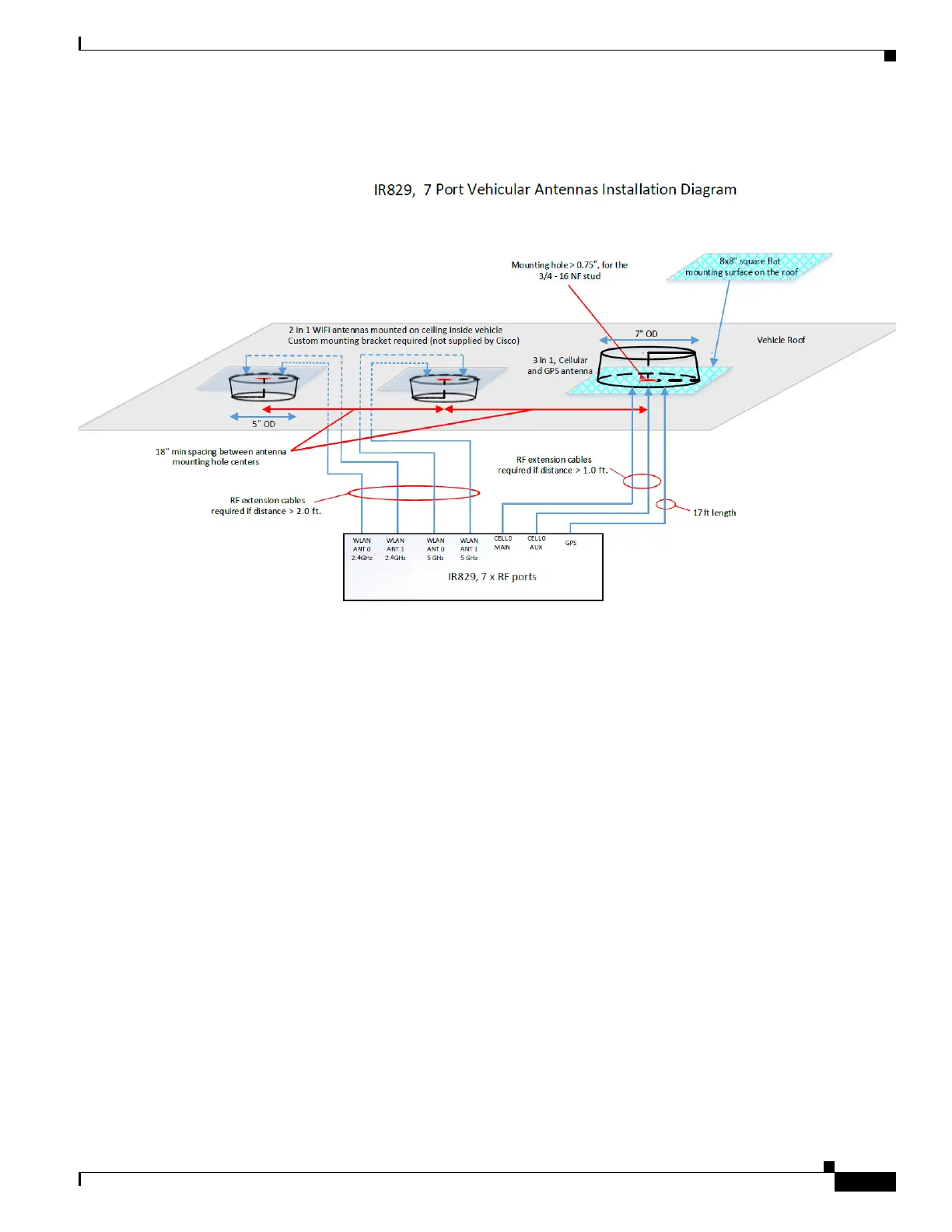
Figure 1-8 Sample Installation
Installation
Users need to provision a 8 x 8" flat mounting surface with a mounting hole on the roof of the vehicle
for the 5-in-1 antenna, and a 6 x 6" flat mounting surface with a mounting hole for the 2-in-1 WiFi
antenna. Without a flat mounting surface, the antenna will not meet IP67 standards and may have
reduced service life.
Ground plane
Cisco recommends having a 1 foot ground plane under both the 5-in-1 and 2-in-1 antennas. In case of a
metal vehicle roof, the roof itself shall be the ground plane. While Cisco has investigated the effects of
ground plane and no ground plane, wireless performance was certified with the 1 foot ground plane.
Isolation between 5-in-1 and 2-in-1 antennas
Cisco recommends 18" inch spacing between the 5-in-1 and the 2-in-1 antenna centers for optimal
isolation.
Cisco recommends routing the 2.4GHz WLAN ports of the IR829 to the 2-in-1 antenna, and the 5GHz
ports to the 5-in-1 antenna to optimize isolation between WiFi 2.4 GHz and cellular 4G LTE. The 5-in-1
antenna has been fully optimized for WiFI and cellular LTE coexistence and isolation. Connecting the
2.4GHz WiFi signals to a separate antenna simply allows to user to optimize the antenna isolation
further. Both the 5-in-1 and 2-in-1 are dual band WiFi capable and fully support both 2.4 GHz or 5GHz
WLAN signals.