11
4
Installation Instructions
4.1
ChooseYour MountingLocation
AgoodmountinglocationisimportanttogettingthebestperformanceoutofyourCW9166I‐MR,
CW9164I‐MRaccesspoint.
Keepthefollowinginmind:
1.
Thedeviceshouldhaveunobstructedlineofsighttomostcoverageareas.Forexample,if
installing
inanofficefilledwithworkspacesdividedbymid‐heightcubiclewalls,installingonthe
ceilingorhigh
onawallwouldbeideal.
2.
PoweroverEthernetsupportsamaximumcablelengthof300ft(100m).
3.
If being used in amesh deployment, theCW9166I‐MR,CW9164I‐MR should have lineof sight to at
least twoother Meraki
devices. For more detailed instructions regarding access point location
selection, reference the Meraki
Network Design Guide (meraki.com/library/product).
4.2
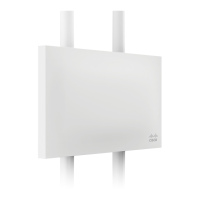
InstalltheCW9166I‐MR,CW9164I‐MR
For most mounting scenarios, the CW9166I‐MR, CW9164I‐MR mount plate provides a quick, simple, and
flexible means of mounting
your device. The installation should be done in two steps. First, install the mount
plate to your selected location.
Then, attach the CW9166I‐MR,CW9164I‐MR to the mount plate.
!!!Thisequipmentisonlysuitableformountingatheights≤2m!!!
4.2.1
AttachtheMountPlate
TheCW9166 I‐MR,CW9164I‐MRmountplatecanbeusedtoinstallyouraccesspointinawiderangeof
scenarios:wallorsolid
ceiling,belowadropceiling,onvariouselectricaljunctionboxes,oraboveadrop
ceiling(in theplenum).
Themountplatecontainsavarietyofholepatternsthatarecustomizedforeachinstallationscenario.The
mountingtemplate(includedinboxwithmountplate)shouldbeusedtodrillholesforwallmountsandalso
to
identifythecorrectholepatternsinthemountplatethatshouldbeusedforeachtypeofmount .
Thefollowingimagesalsoshowtheholepatternsthatshouldbeusedforeachtyp eofmoun t:
 Loading...