12
Unpacking and Installing the Cisco ONS 15454 Four-Shelf and Zero-Shelf Bay Assembly
78-13271-05
Installation Instructions
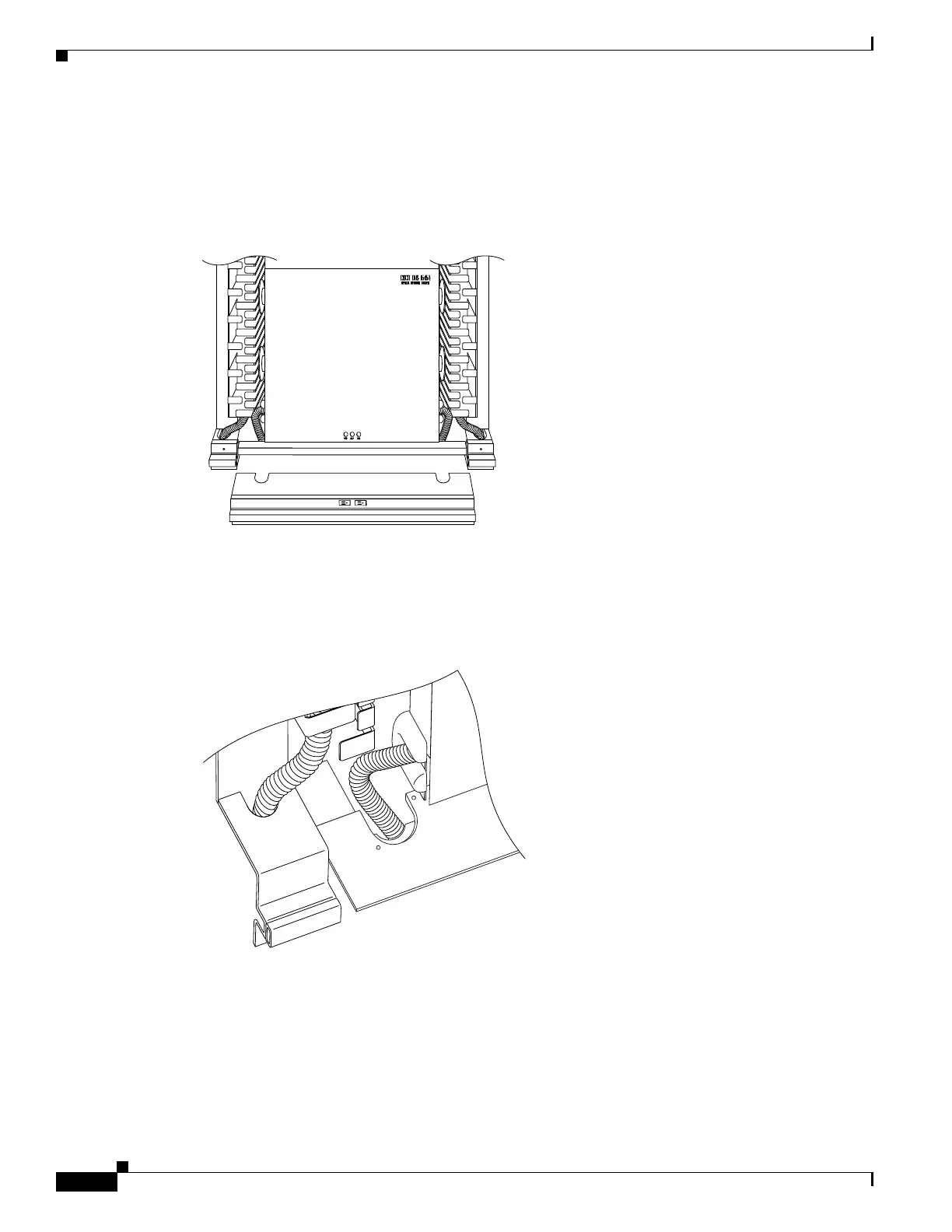
Step 2 To route fiber, remove the two top covers on the base plate or extender base by unscrewing the two
screws on the covers, as shown in Figure 8.
Figure 8 Base plate with two top covers removed
When the covers have been removed, you have access to the base of the rack and any holes previously
cut into the raised floor tile, as shown in Figure 9.
Figure 9 Raised floor base fiber routing close-up
You can use the base plate or extender base holes to route the fibers. Cisco recommends using the base
plate holes for the bottom node and the extender base holes for the other three nodes on the four-node
rack.
All electrical cables will be routed in the back of the rack in the extender bases. Holes should already be
cut out in the raised floor tile to compensate for any DS1, DS3, ground and power cables.
61968
61967

 Loading...


